
Display panel and display module

A display panel and display area technology, applied in nonlinear optics, instruments, optics, etc., can solve the problems of blurred camera imaging under the screen, serious liquid crystal phase diffraction effect, etc., to reduce the degree of blur, improve the diffraction phenomenon, and improve the imaging quality. Effect

Active Publication Date: 2021-07-20
SHENZHEN CHINA STAR OPTOELECTRONICS SEMICON DISPLAY TECH CO LTD
View PDF14 Cites 0 Cited by
  • Summary
  • Abstract
  • Description
  • Claims
  • Application Information

AI Technical Summary

Problems solved by technology

[0004] The embodiment of the present invention provides a display panel and a display module to solve the technical problem of blurred imaging of the camera under the screen due to the serious phase diffraction effect of the liquid crystal in the existing liquid crystal display

Method used


Image

  • Display panel and display module
  • Display panel and display module
  • Display panel and display module

Examples


Embodiment Construction

[0029] The technical solutions in the embodiments of the present application will be clearly and completely described below in conjunction with the drawings in the embodiments of the present application. Apparently, the described embodiments are only some of the embodiments of this application, not all of them. Based on the embodiments in this application, all other embodiments obtained by those skilled in the art without making creative efforts belong to the scope of protection of this application.

[0030] In the description of the present application, it should be understood that the terms "first" and "second" are used for description purposes only, and cannot be interpreted as indicating or implying relative importance or implicitly indicating the quantity of indicated technical features. Thus, a feature defined as "first" or "second" may explicitly or implicitly include one or more of said features. In the description of the present application, "plurality" means two or ...


PUM

PropertyMeasurementUnit
Angleaaaaaaaaaa

Abstract

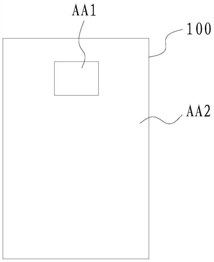
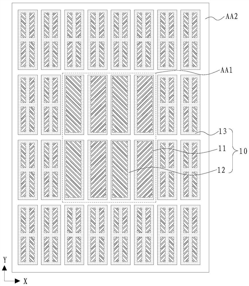
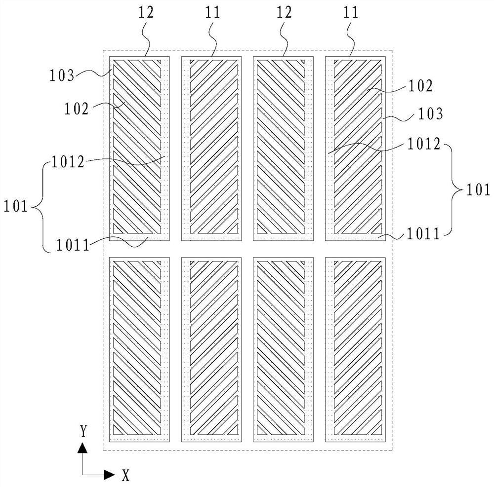
The embodiment of the invention discloses a display panel and a display module, the display panel comprises a first display area and a second display area, the display panel comprises a pixel electrode layer, and the pixel electrode layer comprises a plurality of first pixel electrodes and a plurality of second pixel electrodes which are distributed in the first display area in an array mode. The first pixel electrodes and the second pixel electrodes are alternately arranged at least along at least one of a first direction and a second direction which are intersected; each of the first pixel electrode and the second pixel electrode comprises a trunk part and a plurality of branch parts connected with the trunk part, the trunk parts divide the first pixel electrodes or the second pixel electrodes into at most two domains, the branch parts in different domains are different in extension direction, the branch parts in the same domain are the same in extension direction, and the extension direction of the branch part in one domain of any first pixel electrode is different from the extension direction of the branch part of the corresponding domain of the adjacent second pixel electrode. The liquid crystal grating period is increased, the diffraction phenomenon can be improved, and the imaging quality of the under-screen camera is improved.

Description

technical field [0001] The invention relates to the field of display technology, in particular to a display panel and a display module. Background technique [0002] With the continuous development of electronic technology, cameras are more and more widely used in various electronic devices. However, the appearance of the camera is inconsistent with the surrounding environment, and it is easy to be observed, which greatly affects the aesthetics of electronic equipment and is not conducive to the development of full screens. By placing the camera under the liquid crystal display, the aesthetics of the electronic device can be greatly improved, and the degree of freedom in the placement of the camera can be increased. However, due to the low transmittance of the liquid crystal display, the diffraction caused by the periodic liquid crystal arrangement greatly affects the imaging quality of the camera under the screen. [0003] To sum up, the structure of the existing liquid c...

Claims


Application Information

Patent Timeline
IPC IPC(8): G02F1/1343
CPCG02F1/134309G02F1/133707
Inventor 冯铮宇
Owner SHENZHEN CHINA STAR OPTOELECTRONICS SEMICON DISPLAY TECH CO LTD
Learn More