[0035] A major
advantage of the invention in combination with the video hologram display known from WO 2004 / 044659 is that before transforming the reference data set for the aggregated wave field in the hologram layer, the area of the observer window(s) in the reference layer can be restricted so that it is considerably smaller than the area of the SLM light modulator matrix. The extent of the observer window maximally corresponds with the periodicity interval in the layer which contains the image of the
light source used for reconstruction, when reconstructing the hologram in the reference layer. This leads to the effect that the computer-generated video hologram according to this invention only needs to realize lower
diffraction angles compared with other solutions, all the more if the data sets for the reference layer and for the hologram layer have the same number of matrix point values. Thanks to the computation of amplitude values for the light modulator matrix, the demands on
processing speed are greatly reduced. In particular, in conjunction with a known position detection and tracking device for tracking the current viewer position, the dimension of the observer window can be greatly minimized to benefit from this
advantage. Further, WO 2004 / 044659, as noted earlier, requires computationally intensive operations performed on every
single point in the scene to be reconstructed. With the present invention, it is no longer necessary to perform a computationally intensive operation on every single
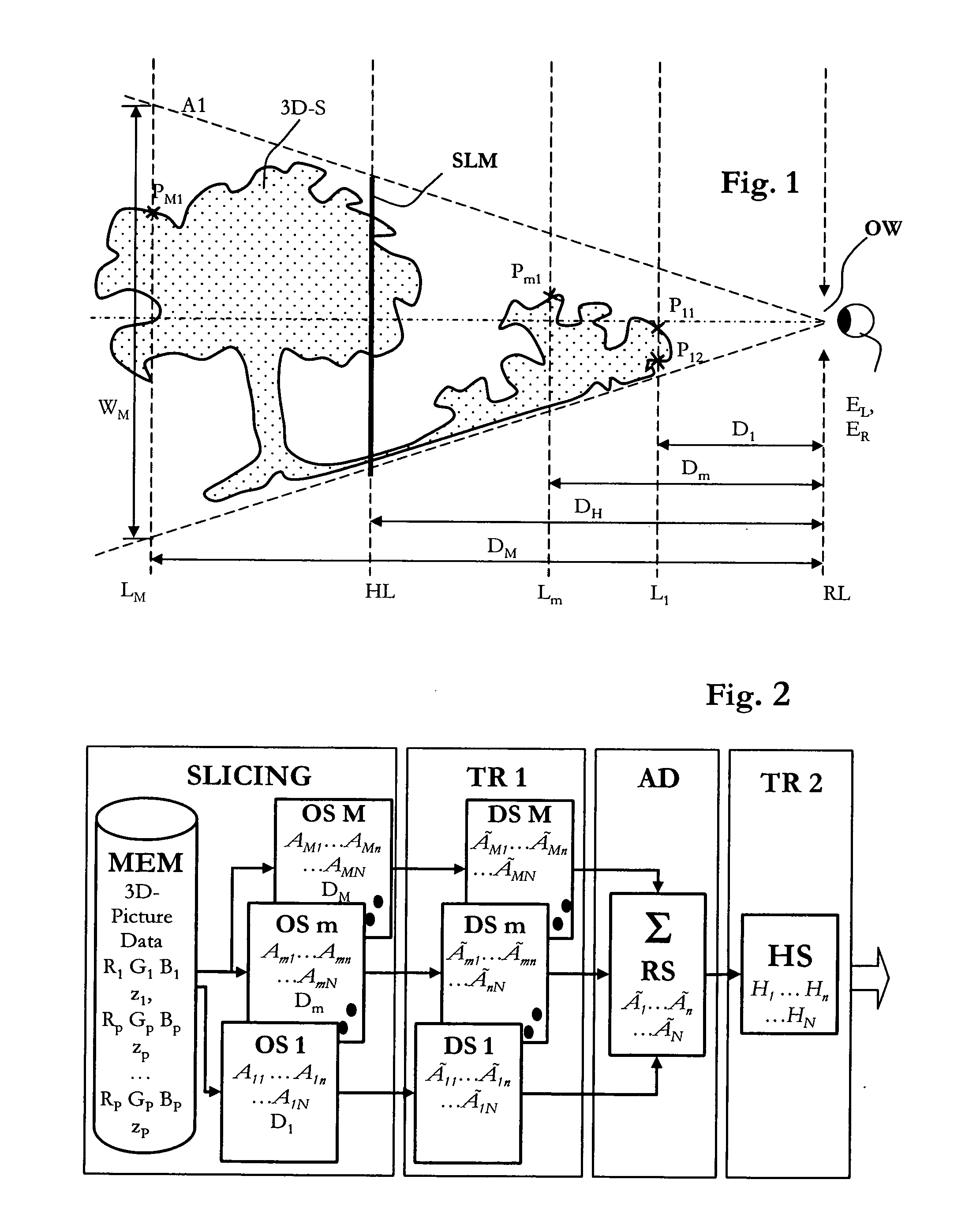
object point; instead, the first transformation (from each section layer to the virtual observer window in the
reference plane—where the observer's eyes will be) is performed on entire section
layers, rather than each individual object points in a layer. The second transformation going back from the virtual observer window to the hologram layer is even more efficient since it is just a single operation, yet encodes information for all object points.
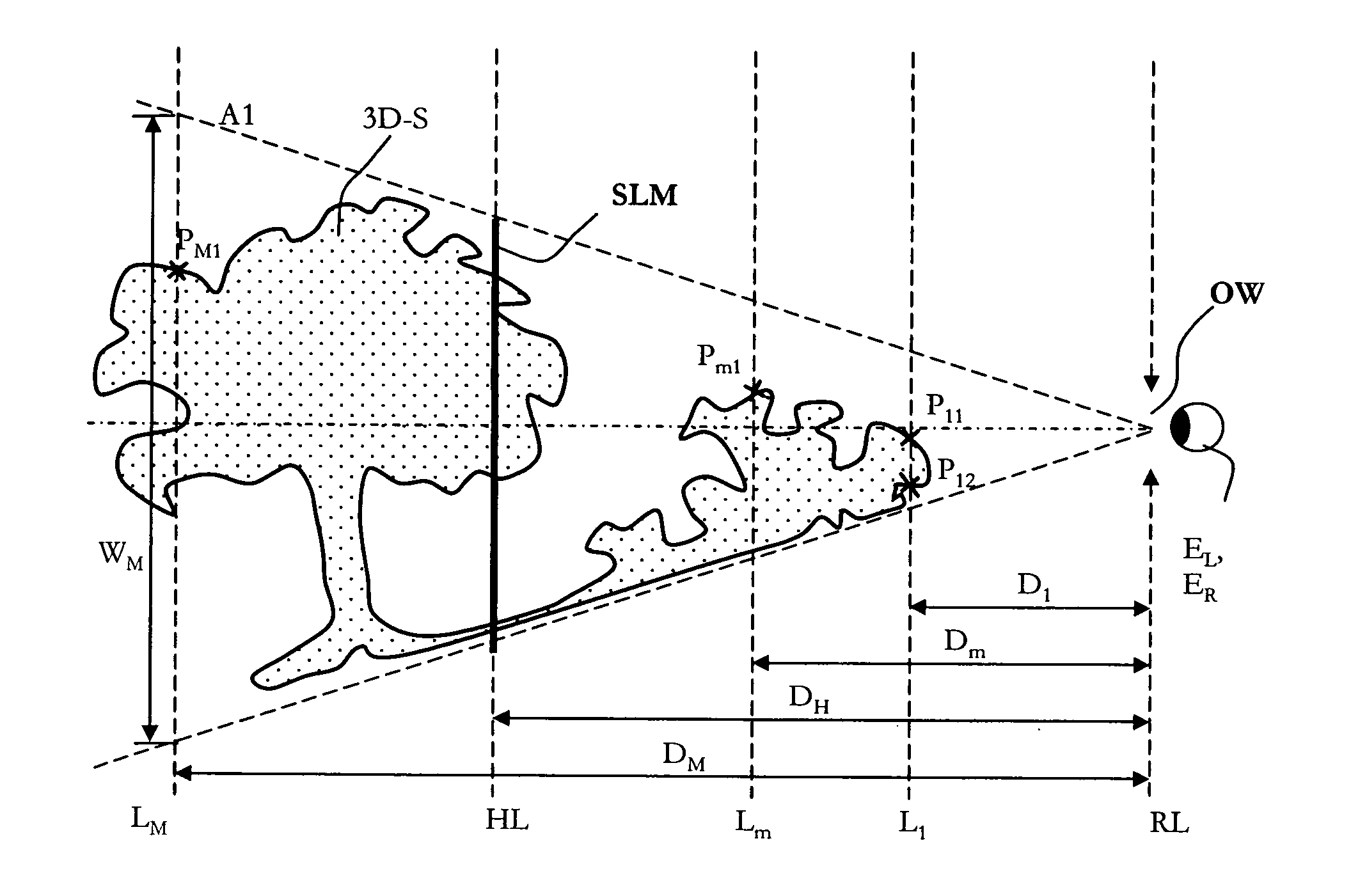
[0036] In a further embodiment of this invention, each object data set of the section layers is based on a virtual area size which depends on its distance to the reference layer. The section layer areas result from imaginary faces running from the edges of the respective observer window to the edges of the SLM of the video hologram. Because of the same number of matrix point values in each data set, the area assigned to the individual matrix points changes in proportion to the distance to the reference layer. Assigning the original object data to the object data sets of the section layers that is also known as
slicing, leads to assigning the discrete
object point values of the scene to a respective matrix point of a two-dimensional coordinate
system that describes the matrix points on the respective section layer. According to the local position of the object points with respect to the section layers, the original object information is thereby assigned to the matrix points of the coordinate
system which is closest to their spatial position. The distance-dependent areas of the section layers thus lead to the effect that the area-dependent
object point resolution to describe a section layer of a scene is larger the closer the section layer is situated to the reference layer. This means that while the foreground of a scene is reconstructed in detail, the same scene element in the background would be reconstructed at a much lower resolution. However, the more distant virtual section layers can reconstruct a much larger viewing area for the background of the scene. This kind of reconstruction of a scene provides a very natural representation of foreground and background elements of a scene on the one hand and helps minimizing the required computing power on the other.
[0037] In a preferred embodiment of this invention, the value for the distance of each object data set of the virtual section layers can be chosen or changed before transformation so that the entire reconstruction or parts of it appear in front of or behind the hologram layer. This way, both a
natural position of the reconstruction in the depth of the space in front of the viewer's eyes and a deliberate amplification or reduction of the
depth effect of a synthetic video hologram can be realized through
software settings alone.
[0038] When encoding according to the prior art method known from WO 2004 / 044659, the reconstructed three-dimensional scene appears in the
free space in front of the viewer's eyes in the form of a wave field controlled by the light modulator matrix. The imaginary section layers used for computing also define the position of the reconstruction in the space in front of the observer windows and are situated at a finite distance to the reference layer. According to the conditions prevailing in an optical near field, this causes the light contribution of each light point, of the holographically reconstructed scene to the aggregated wave field, to propagate as a
spherical wave to provide a contribution to the target wave front in the observer window in the reference layer. The transformation of each object data set in the reference layer can thus be expressed with adequate approximation by a Fresnel transform. For this, the amplitude values of all object points of all object data sets are multiplied with a Fresnel
phase factor, which depends on the distance of the respective section layer to the reference layer.
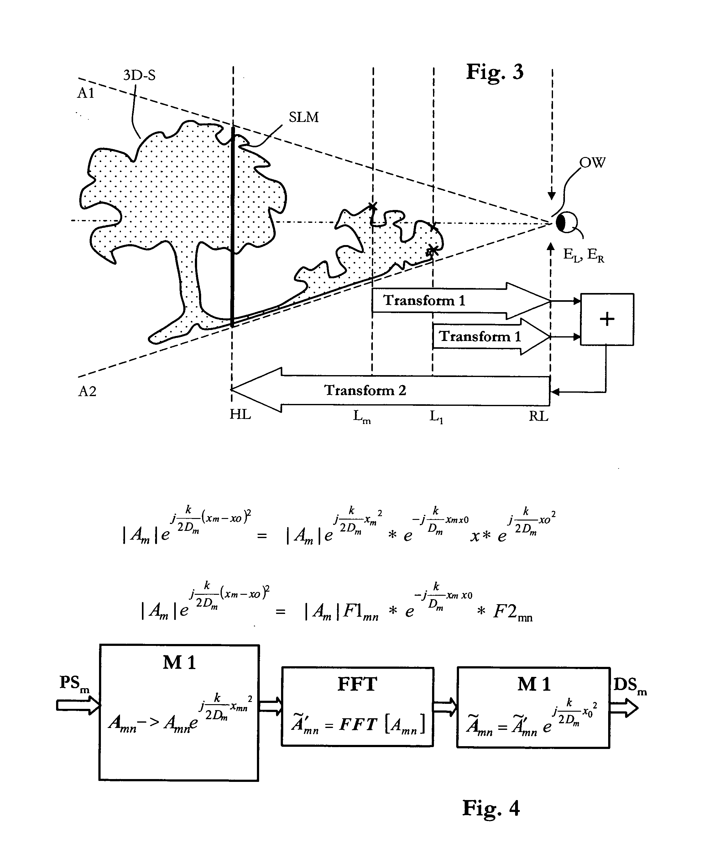
[0039] The Fresnel
phase factor has an exponent which depends on the squared difference of the coordinates between each original section layer and reference layer and other factors. Much
processing time and computing power are thus required to perform the many Fresnel transformations. According to a preferred embodiment of this invention, this
disadvantage is compensated by dividing the difficult Fresnel transformations into individual steps so that these steps can be performed with the help of fast Fourier transformations (FFI) in conjunction with further processing steps in the form of multiplications with
spherical wave factors. This method has the
advantage that dedicated
electronic hardware such as
graphics and / or
holography adapters can be used for computing video holograms. Such hardware includes at least one dedicated
graphics processor with known modules for
slicing and other
video processing steps, such as image rendering, and at least one specific processor module for performing the Fresnel transformations with the help of fast Fourier transformation routines. Such processors in the form of
digital signal processors (DSP) with the required FFT routines can be made inexpensively using known methods. Recent advantages in common
graphics processors enable operations such as Fourier transforming the data of the section layers into the reference layer using so called shading algorithms.
[0040] In order to simplify the computation of the wave fields, the transformation which describes the propagation of light between the original section layer and the reference layer is modified such that it comprises a Fast Fourier Transformation (FFT) and two multiplications with phase factors describing spherical
waves. The first
phase factor depends on the coordinates in the original section layer and on the distance between original section layer and reference layer. The second phase factor depends on the coordinates in the reference layer and on the distance between the original section layer and the reference layer. Depending on the collimation of light in the optical
system one or both of these phase factors may be set to a constant value.

