Spacecraft image decomposition and transmission method

A transmission method and spacecraft technology, applied in the field of spacecraft image transmission, can solve the problems of increasing data volume, complex processing equipment, increasing the complexity of spacecraft, etc., and achieve the effect of improving anti-error performance and simple and reliable method

Active Publication Date: 2010-12-29
BEIJING SHENGAN TONGLI TECH DEV CO LTD
View PDF5 Cites 10 Cited by
  • Summary
  • Abstract
  • Description
  • Claims
  • Application Information

AI Technical Summary

Problems solved by technology

[0004] For the above-mentioned first method, not only a large memory is needed, but also a very high-speed large-scale integrated circuit processing chip (FPGA and DSP, etc.), which will cause difficulties in the realization of data processing equipment on the spacecraft. Data transmission system equipment, especially space processing equipment brings a lot of pressure
For the above second method, the anti-noise ability of the block transmission will be deteriorated, and in order to improve the transmission reliability, sometimes the error correction coding technology has to be used, but it increases the amount of transmitted data
For the above third method, due to the complex processing, it will increase the complexity of the implementation on the spacecraft
In fact, due to the single event effect in space, many on-board processing devices can only be implemented with ASICs. However, due to the limited scale of ASICs, the processing devices should not be too complex and the processing speed should not be very high.
In short, none of the above three methods can simply and reliably realize the on-demand transmission and distribution of images of different quality

Method used


Image

  • Spacecraft image decomposition and transmission method
  • Spacecraft image decomposition and transmission method

Examples


Embodiment Construction

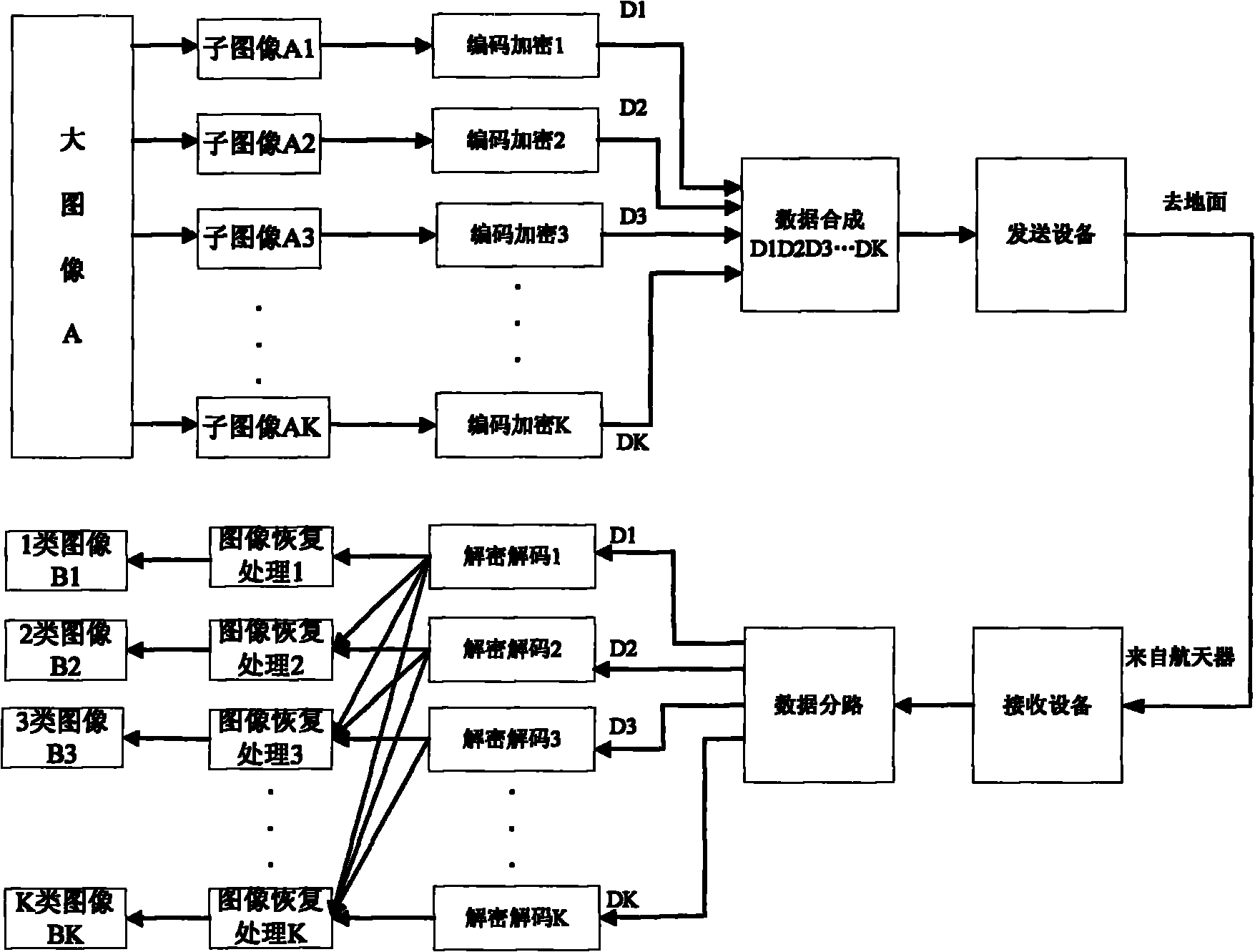
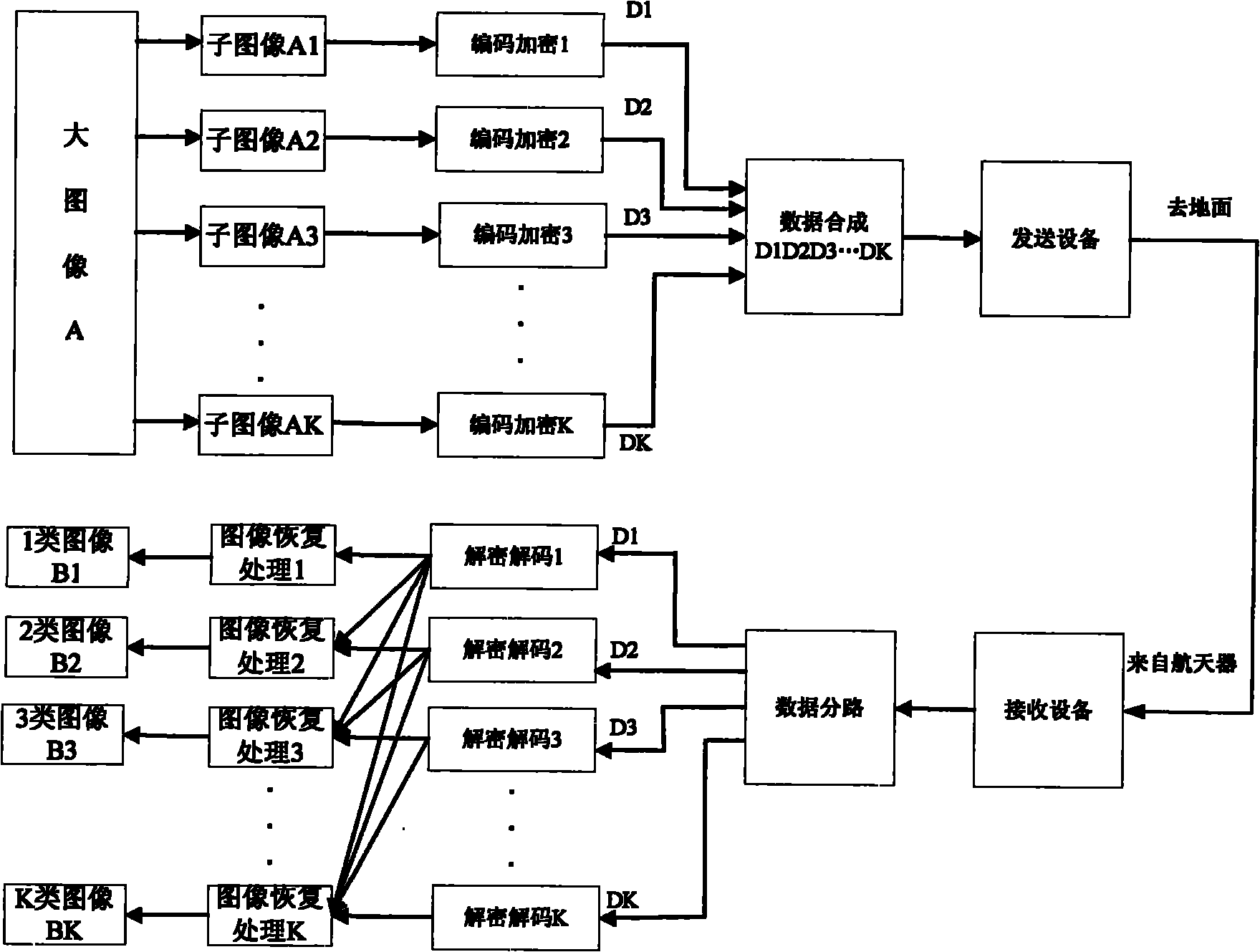
[0026] like figure 1 Shown is the principle block diagram of the spacecraft image decomposition transmission method of the present invention, and the main steps of the present invention are as follows:

[0027] (1) Perform format processing on the original digital image X (size M1*N1), fill it with pixel gray values ​​of adjacent rows or columns to form a digital image A with size M*N, denoted as A( i, j), i=1, 2, ..., M, j = 1, 2, ... N, M and N are all even numbers, assuming that the number of quantized bits per pixel is Q (generally Q=8 ), then the total number of bits of the digital image A is MNQ.

[0028] (2) Decompose the digital image A (i, j) into K sub-images At (i, j), t=1, 2, ... K, K is an even number, and K=M / L1 (K can be divisible M) or K=N / L2 (K can divide N), L1, L2 are positive integers greater than 1; in order to ensure that each sub-image contains the global information of the whole image before decomposition, the present invention adopts when decomposing...


PUM


Abstract

The invention discloses a spacecraft image decomposition and transmission method. In the method, a high-resolution image on a spacecraft is decomposed into a plurality of non-overlapped sub-images containing overall information of the original image; the sub-images are synthesized by using different encoding and encrypting modes and then transmitted; error codes do not have great influence on the overall image during the transmission; and data is distributed to K-class users with different requirements on image quality on ground, so that the images received by different users have different qualities, namely the users of high authority class acquire the images with high qualities, and the users of low authority class acquire the images with low qualities. Certain compression effect can be achieved by the method instead of conventional image compression modes, so the complexity of processing and transmission equipment on the spacecraft is greatly reduced; and meanwhile, the complexity of the ground image processing and restoring equipment is not changed, so the efficiency and the safety of image transmission of the spacecraft are improved and the images with different qualities are distributed as required.

Description

technical field [0001] The invention belongs to the field of communication, and relates to a spacecraft image transmission method. Background technique [0002] With the development of space remote sensing and earth observation technology, the image resolution acquired by spacecraft is getting higher and higher, and the raw data rate is getting higher and higher, which can reach hundreds of Mbps to tens of Gbps. The image quality is getting higher and higher, the usage is wider and wider, and there are more and more users; even if the image resolution is artificially reduced, the quality of the obtained image is still quite high, and the image still has a very high utilization value. If the original image of the spacecraft is not effectively preprocessed and transmitted efficiently, it will be difficult to ensure the image quality obtained on the ground, and it is also difficult to ensure that images of different quality levels are obtained on the ground at the same time, an...

Claims


Application Information

Patent Timeline
Patent Type & Authority Applications(China)
IPC IPC(8): H04N7/26H04N7/30H04N7/46H04N19/423H04N19/46H04N19/59
Inventor 周诠黄普明肖化超李敏奇张毅
Owner BEIJING SHENGAN TONGLI TECH DEV CO LTD
Why Eureka
Try Eureka