Polarizing film mask slice with high resolution

A high-resolution, polarizing film technology, used in optics, instruments, photolithography on pattern surfaces, etc., can solve the problem of high manufacturing cost, inability to guarantee high-quality imaging, optimal phase shifter design, and difficulty in placement Large and other problems, to achieve the effect of convenient production, reducing proximity effect, and improving lithography resolution

Inactive Publication Date: 2005-04-20
INST OF OPTICS & ELECTRONICS - CHINESE ACAD OF SCI
View PDF0 Cites 3 Cited by
  • Summary
  • Abstract
  • Description
  • Claims
  • Application Information

AI Technical Summary

Problems solved by technology

The application of phase-shift mask technology has improved the resolution to some extent, but with the reduction of the basic period of the lithography line, the phase-shift mask cannot guarantee high-quality imaging; and the design of the optimal phase shifter, The location is difficult to place, the manufacturing cost is high, and the above-mentioned deficiencies are difficult to meet the needs

Method used


Image

  • Polarizing film mask slice with high resolution
  • Polarizing film mask slice with high resolution
  • Polarizing film mask slice with high resolution

Examples


Embodiment Construction

[0025] Below the present invention will be described in further detail in conjunction with accompanying drawing:

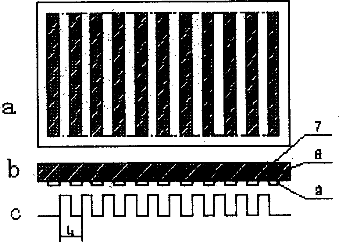
[0026] Such as figure 1 a, 1b, and 1c show conventional masks. The light-transmitting regions 8 and the opaque regions 9 are alternately arranged to form a mask pattern, and the corresponding mask amplitude transmittance is as follows: figure 1 Shown in c; the amplitude transmittance is relatively high in the light-transmitting region 8, and very low (amplitude transmittance=0) in the light-transmitting region 9, then a pair of adjacent light-transmitting regions 8 and light-impermeable regions 9 The basic period L that makes up the mask pattern 1 .

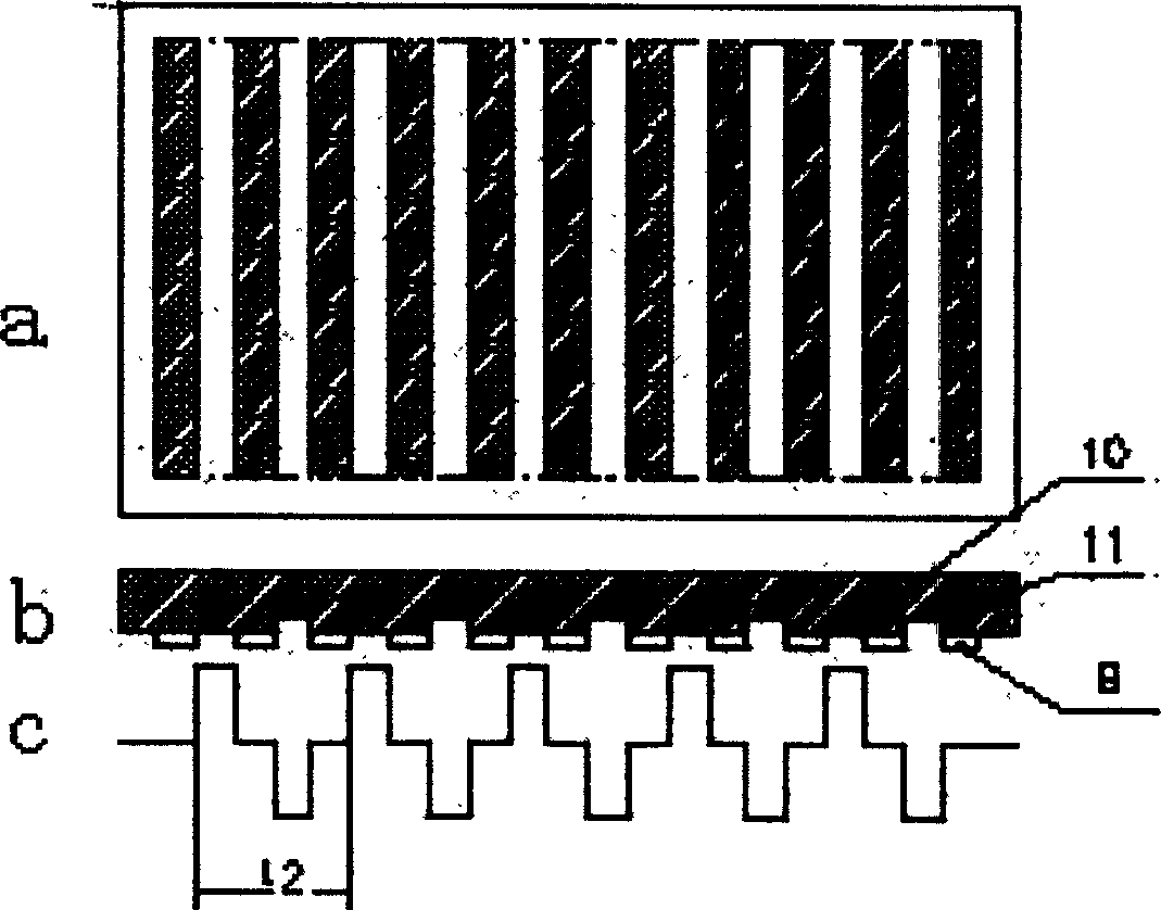
[0027] Such as figure 2 a and 2b are schematic diagrams of the structure of the phase shift mask. There is a phase shift layer at the light-transmitting region 11, and the phase of the imaging beam passing through the adjacent light-transmitting regions 10 and 11 of the light-impermeable region 9 will have a 18...


PUM


Abstract

A polarized film high resolution mask plate characterizes in covering a layer of polarized film on a relevant zone of the mask to enable the transmission zone adjacent an non-transmission zone to transmit line polarized imaging beams with mutual vertical polarization directions (or inversed rotation round polarization imaging beams, or those elliptical inversed rotation and mutual vertical major axis) to integrate the polarization film and traditional mask plate to enable the mask plate itself to have the function of output polarized light to increase the basic period of mask pattern and reduce the diffraction angle of imaging beams and adjacent effect to increase photo-etching resolution used in deep sub-micron and nm projecting lithography.

Description

Technical field [0001] The invention is a novel polarizing film high-resolution mask plate, which belongs to the further optimization and improvement of the structure of the mask plate in the projection optical lithography system. Background technique [0002] The schematic diagram of the traditional mask structure is as follows: figure 1 As shown, the light-transmitting regions 8 and the opaque regions 9 are alternately arranged to form a mask pattern, and the corresponding mask amplitude transmittance is as follows: figure 1 as shown in c. [0003] In recent years, in order to improve the resolution of projection optical lithography, a phase-shift layer that changes the phase of the imaging beam has been designed in a specific area of ​​the mask plate for light transmission. There are many types of such phase-shift masks. figure 2 What is shown is a schematic structural diagram of a phase shift mask. There is a phase shift layer at the light-transmitting region 11 , an...

Claims


Application Information

Patent Timeline
Patent Type & Authority Applications(China)
IPC IPC(8): G02B27/28G03F1/26G03F1/36G03F7/20
Inventor 余国彬姚汉民罗先刚严佩英胡松刘业异
Owner INST OF OPTICS & ELECTRONICS - CHINESE ACAD OF SCI
Why Eureka
Try Eureka