Separation type earthquake reduction and insulation pile group foundation

A technology of pile group foundation and seismic reduction and isolation, which is applied in the direction of foundation structure engineering, protective devices, buildings, etc., can solve the problems of high cost of seismic isolation devices, increase in engineering construction costs, and unsatisfactory improvement effects, so as to achieve reasonable force, The effect of saving engineering cost and reducing the peak value of earthquake motion

Pending Publication Date: 2020-08-21
JSTI GRP CO LTD
View PDF0 Cites 1 Cited by
  • Summary
  • Abstract
  • Description
  • Claims
  • Application Information

AI Technical Summary

Problems solved by technology

[0003] According to the requirements of the above codes, in areas with seismic fortification intensity of 7 degrees and above, under the earthquake input of E2 level, for the pile group foundation structure of the bridge consolidated in the cap, the pile foundation will often be damaged due to the strong bending moment transmitted to the bottom of the cap. However, it bears a large vertical tensile force, and may even be broken, which will not meet the requirements of the pile foundation as a capacity protection component in the code.
Engineers and technicians in the field reduce the earthquake transmitted from the huge superstructure to the foundation by introducing shock-absorbing and isolating devices (rubber damping bearings, steel damping elements, viscous dampers, etc.) between the superstructure and the substructure of the bridge. However, this method is not ideal for towering bridge towers, bridge piers and continuous rigid frame bridges. Moreover, the shock absorbing and isolating devices are expensive and require regular inspection, maintenance and replacement during the operation period, which greatly increases the construction cost. cost

Method used


Image

  • Separation type earthquake reduction and insulation pile group foundation
  • Separation type earthquake reduction and insulation pile group foundation
  • Separation type earthquake reduction and insulation pile group foundation

Examples


Embodiment

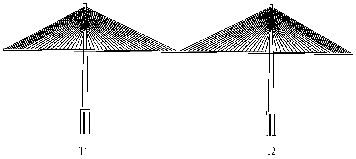
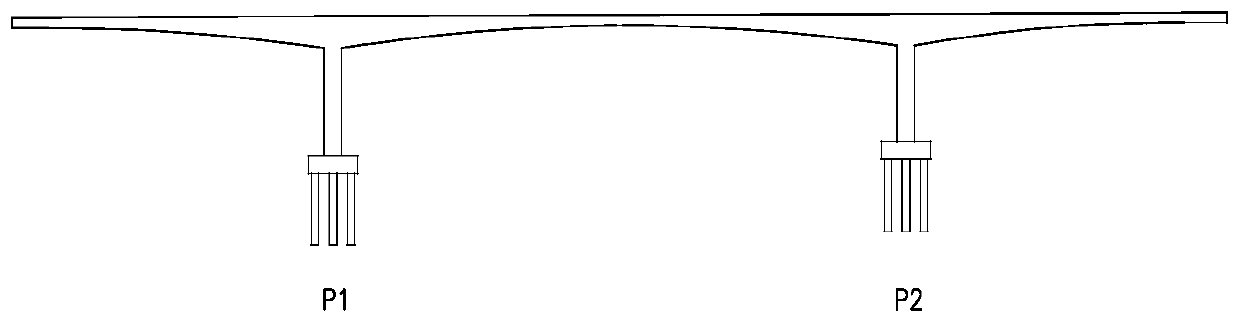
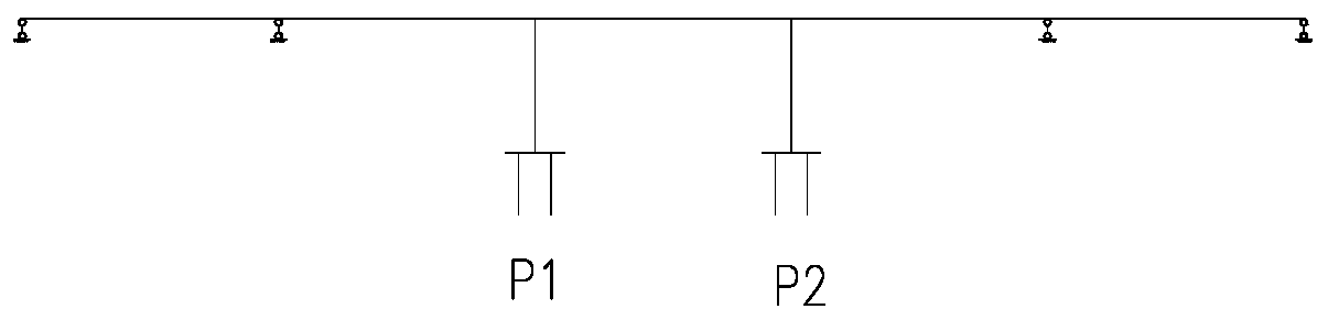
[0036] Such as Figure 1 ~ Figure 3 Shown are several common bridge structure systems, and the present invention has certain applicability.

[0037] Such as Figure 4 ~ Figure 6 As shown, a separate earthquake-absorbing and isolating pile group foundation in the embodiment mainly includes a pier column 1, a cap 2, an earthquake-isolation layer 3 and a pile foundation 4, and the earthquake-isolation layer 3 is located under the cap 2, and the earthquake-isolation layer 3 is poured together with the cap 2 to form a whole, the pier column 1 and the cap 2 are consolidated into one body according to the conventional construction method, and a number of parallel grooves 7 are formed when the vertical formwork is poured for the seismic isolation layer 3, and the grooves 7 are symmetrically arranged vertically and horizontally , and pull through upwards on the longitudinal bridge, the pile group foundation 4 falls in the groove 7 in units of a row (column).

[0038] In order to give...


PUM


Abstract

The invention discloses a separation type earthquake reduction and insulation pile group foundation. The separation type earthquake reduction and insulation pile group foundation comprises pier studs,a bearing platform and a pile foundation, an earthquake insulation layer is mounted between the top of the pile foundation and the bearing platform, the pile foundation is located in a parallel groove in the earthquake insulation layer, and can freely slide in the earthquake insulation layer, the pier studs and the bearing platform, and the earthquake simulation layer and the bearing platform areconnected into a whole through common steel reinforcing rib embedding and integrated pouring, the foundation is simple and creative in construction, stress is more reasonable, a normal use function of the pile group foundation and the bearing platform can be met, separation of the pile group foundation and the bearing platform under the strong earthquake can be achieved, the structure basic period can be prolonged, the earthquake moving peak value of the structure is effectively reduced, the pile foundation is extremely small damaged and even is not damaged under the earthquake, the bridge structure earthquake resistance capacity is greatly improved, the pile foundation rib distribution rate is reduced, the design of a pile foundation steel pile casing and earthquake reduction and insulation supports can be omitted, and engineering cost is saved.

Description

technical field [0001] The invention belongs to the technical field of bridge engineering, and in particular relates to a separated shock-absorbing and isolating pile group foundation. Background technique [0002] With the frequent occurrence of earthquakes all over the world in recent years, the seismic design of bridges based on lifeline engineering has attracted much attention. With the continuous accumulation of understanding of earthquake damage, the codes and methods for seismic design of bridges at home and abroad have been continuously improved. The "Detailed Rules for Seismic Design of Highway Bridges" (JTG / T B02-01-2008) and "Code for Seismic Design of Highway Engineering" ( JTG B02—2013) and "Code for Seismic Design of Urban Bridges" (CJJ 166—2011), both explicitly proposed a performance-based seismic design method for two-level fortification. [0003] According to the requirements of the above codes, in areas with seismic fortification intensity of 7 degrees an...

Claims


Application Information

Patent Timeline
Patent Type & Authority Applications(China)
IPC IPC(8): E02D27/14E02D27/42E02D31/08
CPCE02D27/14E02D27/42E02D31/08E02D2250/0023E02D2300/0001E02D2300/002
Inventor 郭红雨
Owner JSTI GRP CO LTD
Why Eureka
Try Eureka