

Offset printing method and printing apparatus using the same
a printing plate and offset printing technology, applied in the field of new offset printing methods and printing plates, can solve the problems of insufficient resolution, unsatisfactory image quality of printed images, and foregoing simple methods, and achieve the effect of satisfying identifying characteristics and easy making of printing plates
- Summary
- Abstract
- Description
- Claims
- Application Information
AI Technical Summary
Benefits of technology
Problems solved by technology
Method used
Image

Examples
first embodiment
1. First Embodiment
A first embodiment of the present invention will now be described.
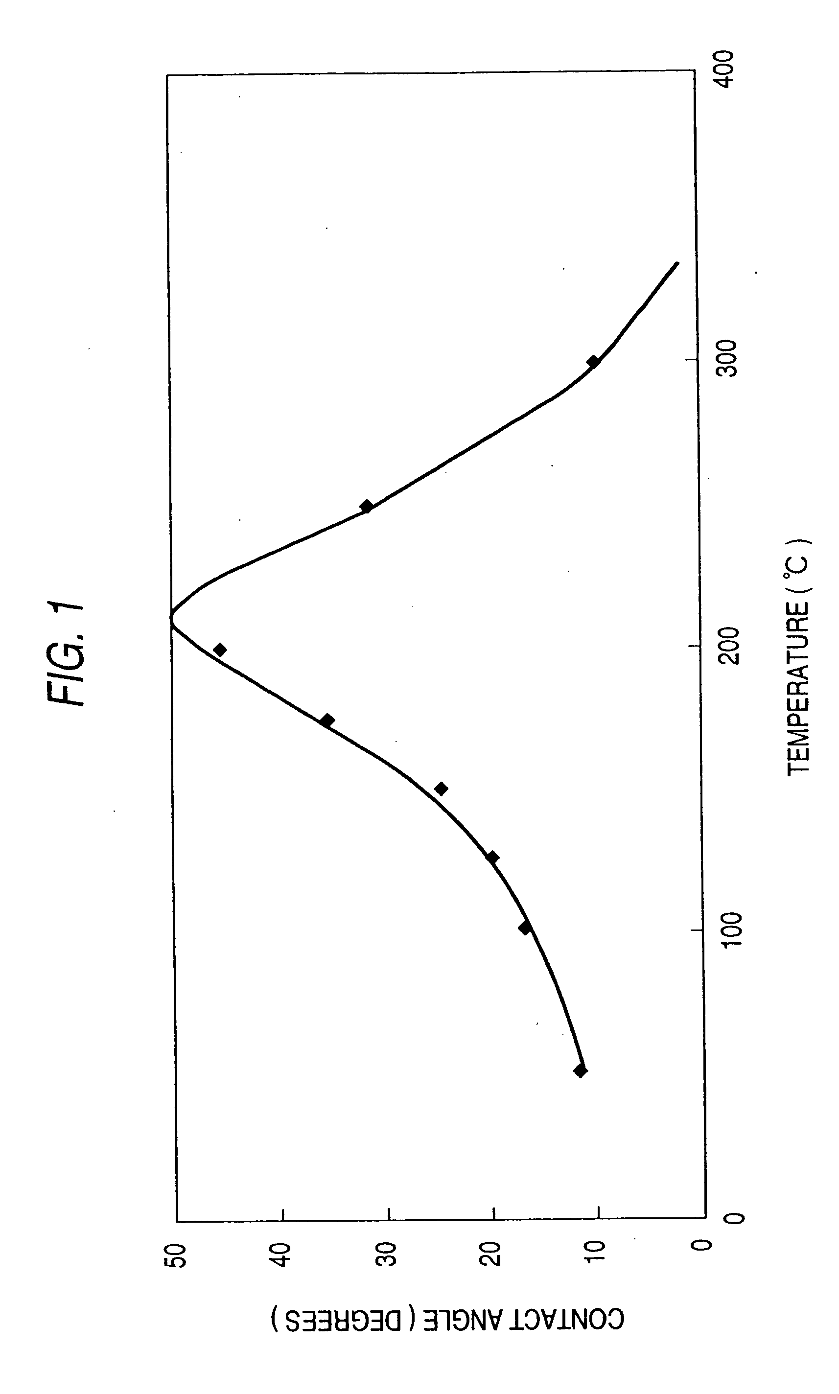
1-1. Thermal Responsive Substance
Initially, the “thermal responsive substance” according to the present invention will now be described. The thermal responsive substance has been defined as the substance having the characteristics (1), (2) and (3). A multiplicity of metal and metal oxide including ceramic and semiconductors which are employed as functional materials have the foregoing characteristics. The thermal responsive ceramic is composed of composite metal oxide, while a major portion of the thermal responsive semiconductors is detected in both of intrinsic semiconductors, such as silicon and germanium having close ground levels and conductivity and extrinsic semiconductors, such as vanadium oxide, which depend on the impurity level. The foregoing ceramic and semiconductors similar to the other metal oxide and metal from a viewpoint of the thermal responsibility of the substance for use i...
second embodiment
2. Second Embodiment
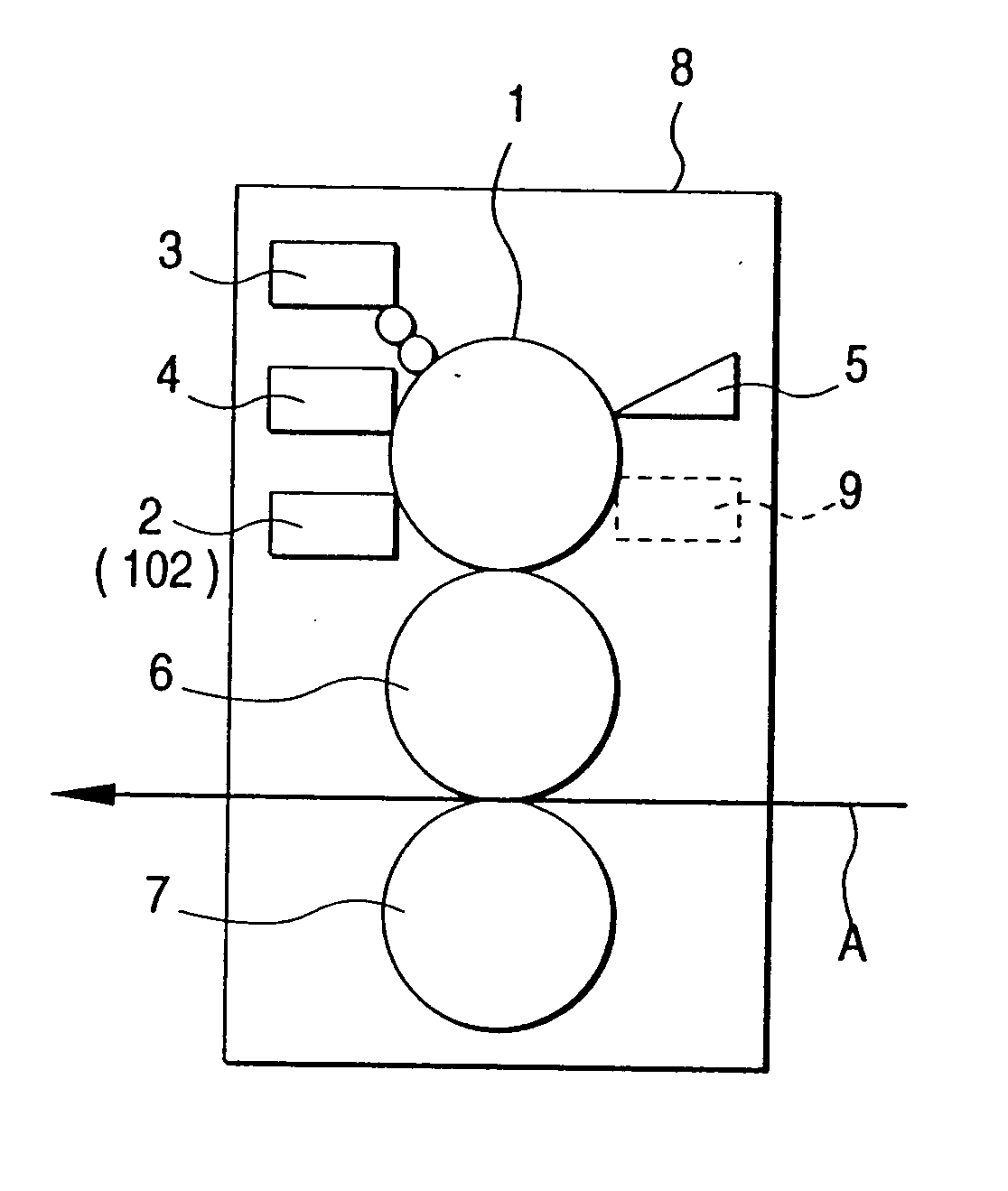
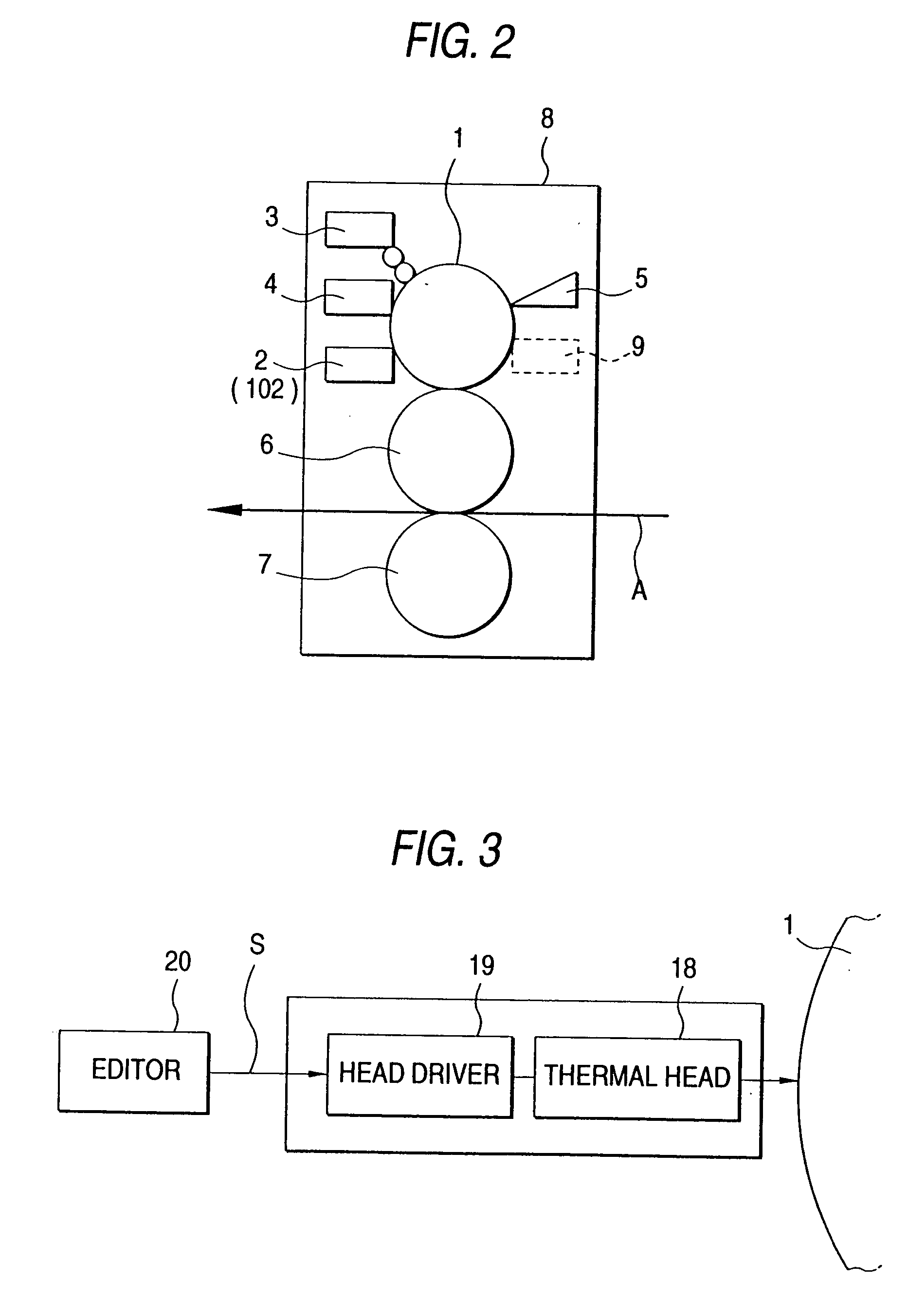
FIG. 6 is a diagram showing an offset printing apparatus according to a second embodiment of the present invention. The offset printing apparatus shown in FIG. 6 incorporates four printing units 11Y, 11M, 11C and 11B each of which is the offset printing apparatus shown in FIG. 2 and which are in series disposed in a body 12. Thus, Y (yellow), M (magenta), C (cyan) and B (Black) ink is used to perform color printing.
Since the structure and operation of each of the printing units 11Y, 11M, 11C and 11B are the same as those of the offset printing apparatus shown in FIG. 2, they are omitted from description. The second embodiment is different in that ink in Y (yellow), M (magenta), C (cyan) and B (Black) is supplied to the ink / dampening water supply unit of each of the printing units 11Y, 11M,11C and 11B.
The operation of the second embodiment will now be described.
In the printing units 11Y, 11M, 11C and 11B, electric power is supplied to the heating resistors i...
third embodiment
3. Third Embodiment
A third embodiment of the present invention will now be described.
FIG. 7 is a diagram showing the structure of an offset printing apparatus according to a third embodiment of the present invention. FIG. 8 is an enlarged view showing an essential portion shown in FIG. 7. The offset printing apparatus shown in FIG. 7 incorporates the offset printing apparatuses each of which is shown in FIG. 2 and which are, in the body 15, disposed as printing stations 14Y, 14M, 14C and 14B around the impression drum 7. Thus, ink in Y (yellow), M (magenta), C (cyan) and B (Black) is used to perform color printing.
The structures of the printing stations 14Y, 14M, 14C and 14B are the same. Therefore, the printing station 14Y is shown in FIG. 7 as a representative station. As shown in FIG. 7 and similarly to the first embodiment, the printing station 14Y incorporates: a printing cylinder 1 having a surface mainly composed of thermal responsive substance, such as titanium oxide or ...
PUM
| Property | Measurement | Unit |
|---|---|---|
| temperature | aaaaa | aaaaa |
| temperature | aaaaa | aaaaa |
| vapor pressure | aaaaa | aaaaa |
Abstract
Description
Claims
Application Information