Optical fiber component

a technology of optical fiber and component, applied in the direction of optics, optical waveguide light guide, instruments, etc., can solve the problems of increasing the cost as a whole, complicated alignment, and high cost, and achieve the effect of reducing the angle of diffraction of light to propagate, reducing the loss of connection, and easy optical coupling

Inactive Publication Date: 2005-10-13
SHOWA ELECTRIC WIRE & CABLE CO LTD
View PDF1 Cites 11 Cited by
  • Summary
  • Abstract
  • Description
  • Claims
  • Application Information

AI Technical Summary

Benefits of technology

[0017] According to the present invention, the optical fiber component can be optically connected to the optical element in the single mode by using the PhC fiber so that the connection loss can be reduced. According to the PhC fiber, moreover, the size of the MFD can be freely designed to expand the core in the single mode and to perform the optical coupling easily according to the design of the optical element. By enlarging the MFD of the PhC fibers, still moreover, the angle of diffraction of the light to propagate can be decreased to reduce the connection loss at the time when the PhC fibers are coupled to the optical element.

Problems solved by technology

However, in case a single mode fiber (as will be shortly called the “SM fiber”) with a small core diameter to align the SM fiber and the bulk type optical device uses the lens contained problems.
Because, these alignment is complicated and spent much time.
Thus, it raises the cost.
However, the GRIN lens system (A) has such a complicated construction as to increase the steps needed for the alignment thereby to raise the cost as a whole.
However, the TEC system (B) uses expensive components and takes a long time for the TEC working, and finds it difficult to adjust the length of the TEC fiber portion.
However, in the GIF system (C), it is difficult to align between the optical device and the optical fiber using GIF with the single mode propagation.
This adjustment of the GI fiber is delicate and difficult for sufficient collimation.
Another problem is that the connection loss increases between the SM fiber and the GI fiber owing to be increasing the difference from the quarter pitch length of GIF.

Method used


Image

  • Optical fiber component
  • Optical fiber component
  • Optical fiber component

Examples


first embodiment

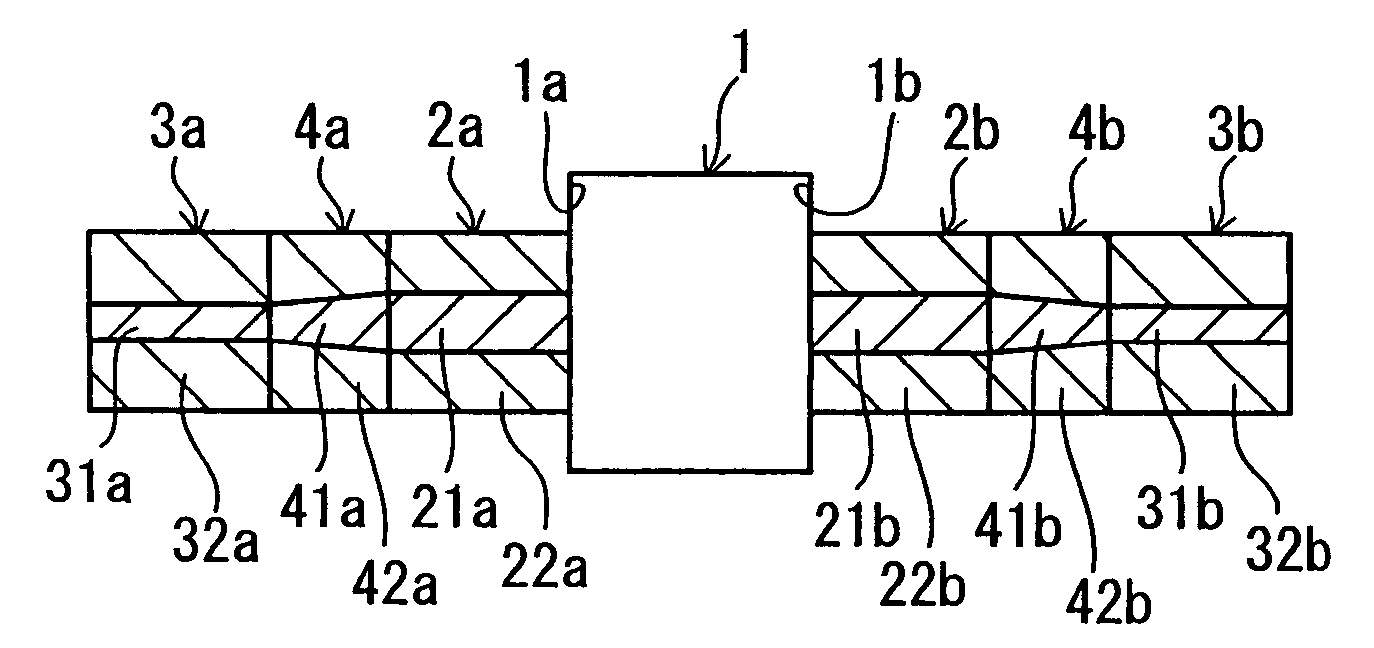
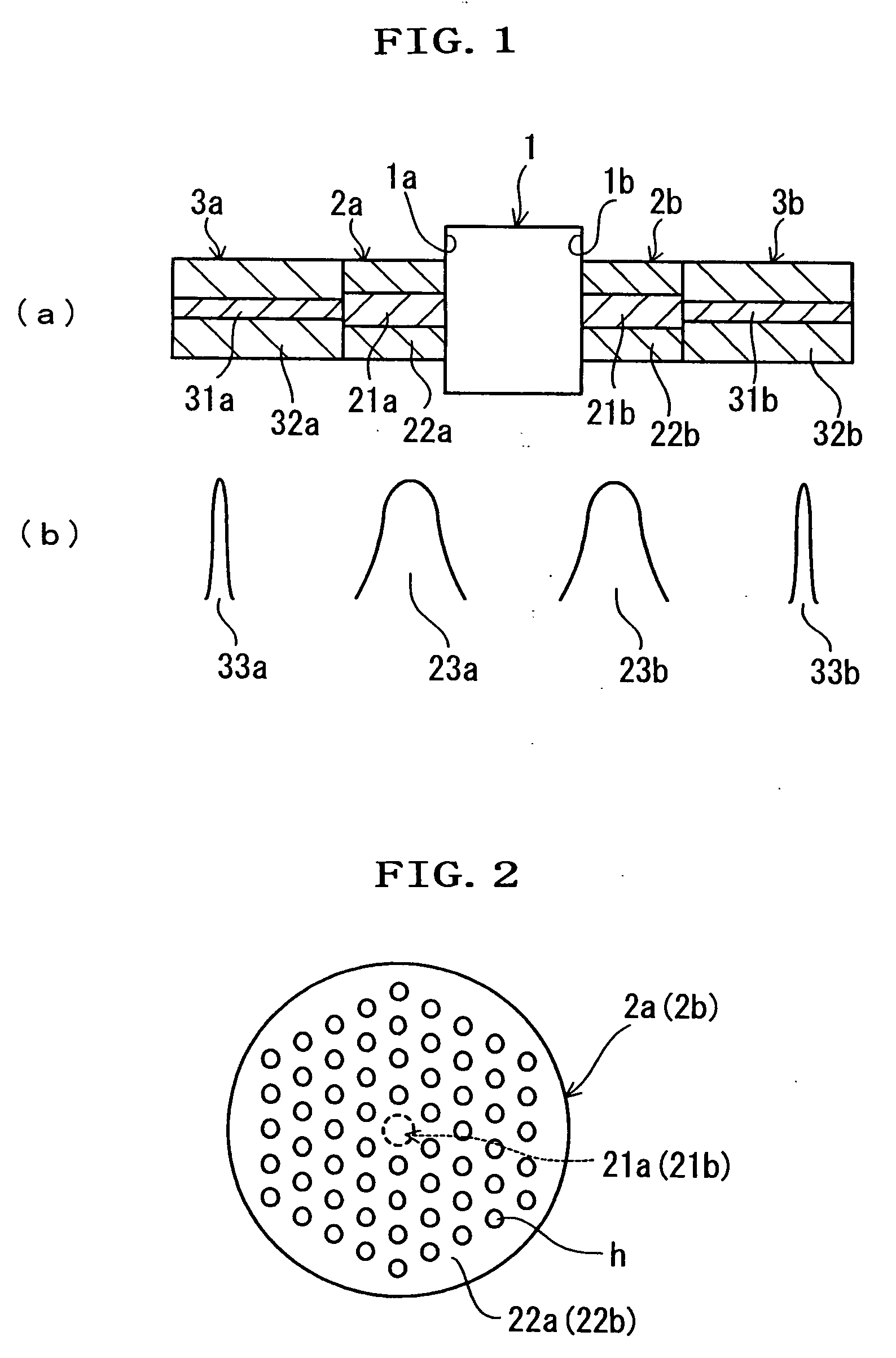
[0032]FIG. 1 is a longitudinal section of a portion of an optical fiber component according to the invention, and FIG. 2 is a transverse section of a PhC fiber.

[0033] In FIG. 1, the optical fiber component of the invention comprises: an optical element 1 made of an optical isolator, an optical filter, an optical switch or an optical variable attenuator, or their combination; a pair of PhC fibers 2a and 2b with a large MFD (approximately 30 to 50 μm); and a pair of SM fibers 3a and 3b with a small MFD (approximately 10 μm). The optical element 1 is provided with a light incident end face 1a on its one side and a light exit end face 1b on its other side. The pair of the PhC fibers 2a and 2b has cores 21a and 21b for propagated light and clads 22a and 22b disposed on the outer peripheries of the cores 21a and 21b. Likewise, the pair of SM fibers 3a and 3b has cores 31a and 31b and clads 32a and 32b disposed on the outer peripheries of the cores 31a and 31b.

[0034] Here, the PhC fiber 2...

second embodiment

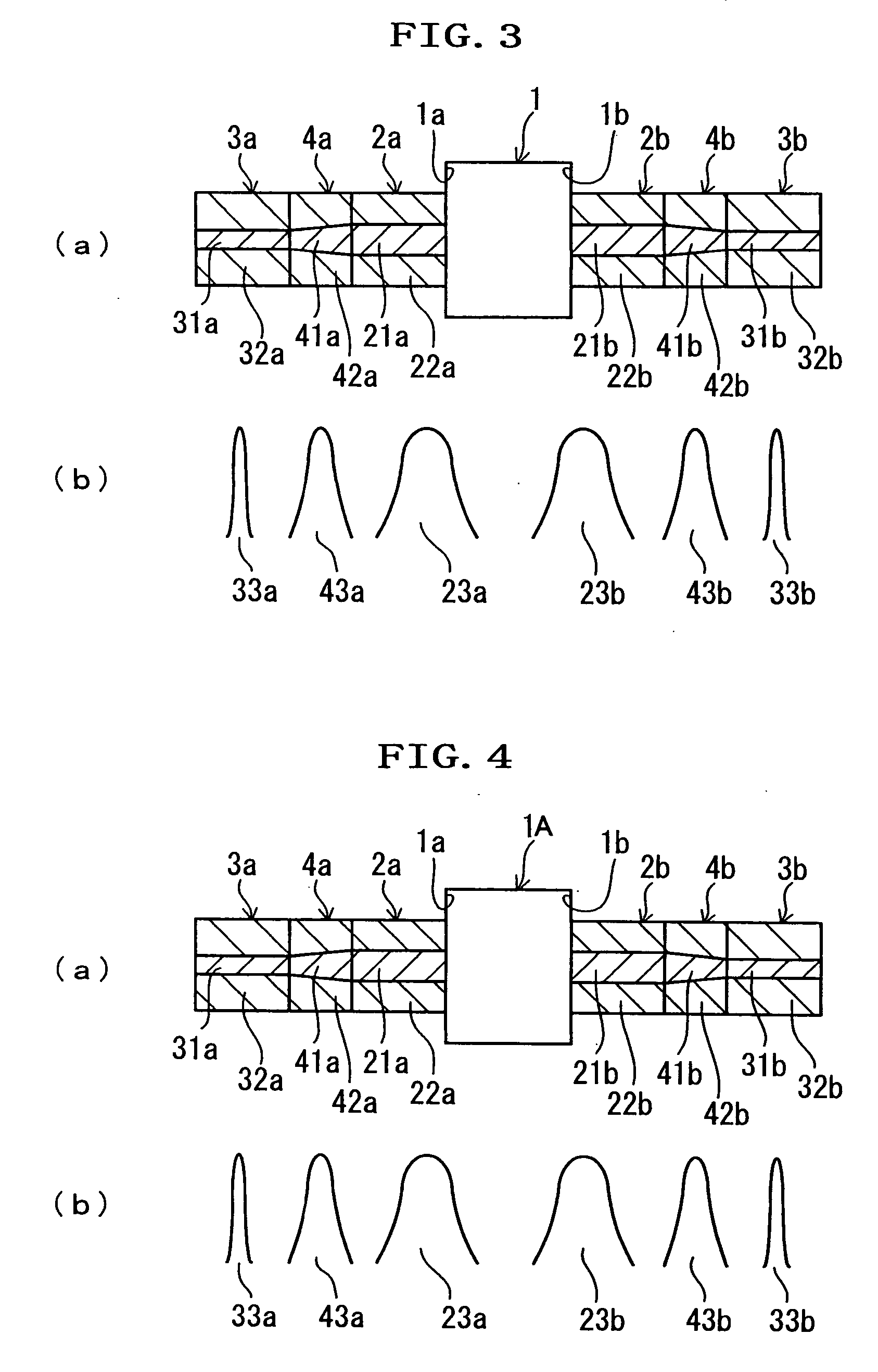
[0039]FIG. 3 presents a longitudinal section of a portion of an optical fiber component according to the invention. From FIG. 3, the portions common to those of FIG. 1 and FIG. 2 are omitted in detailed description by designating them by the common reference numerals.

[0040] In FIG. 3, the optical fiber component according to the second embodiment comprises the optical element 1 having the light incident end face 1a on its one side and the light exit end face 1b on its other side. An end face (or output end) of the first PhC fiber 2a is optically connected to the light incident end face 1a of the optical element 1 while being aligned with the optical axis of the optical element 1. An end face (or input end) of the second PhC fiber 2b is optically connected to the light exit end face 1b while being aligned with the optical axis of the optical element 1. Moreover, an end face (or output end) of a first GI fiber 4a is optically connected to the other end face (or input end) of the first...

third embodiment

[0044]FIG. 4 is an explanatory diagram of an optical fiber component according to the invention. From FIG. 4, the portions common to those of FIG. 3 are omitted in detailed description by designating them by the common reference numerals.

[0045] In the optical fiber component according to the third embodiment, an optical isolator 1A is employed as the optical element.

[0046] Optical measurements on this embodiment have revealed, for a wavelength of 1,550 nm, that the insertion loss between the first and second SM fibers 3a and 3b was 0.5 dB, and that the isolation was 45 dB.


PUM

PropertyMeasurementUnit
mode field diameteraaaaaaaaaa
insertion lossaaaaaaaaaa

Abstract

An optical fiber component comprises an optical element (1), a pair of PhC fibers (2a, 2b) with a large MFD (approximately 30 to 50 μm), and a pair of SM fibers (3a, 3b) with a small MFD (approximately 10 μm). The pair of the PhC fibers (2a, 2b) has cores (21a, 21b) for transmitting light and clads (22a, 22b) provided on the outer periphery of the cores (21a, 21b). An output end of a first PhC fiber (2a) is optically connected to a light incident end-face (1a) of the optical element (1) with the first PhC fiber output-end aligned with the optical axis of the optical element (1). An input end of a second PhC fiber (2b) is optically connected to a light exit end-face (1b) with the second Phc fiber input end aligned with the optical axis of the optical element (1). An output end of a first SM fiber (3a) is optically connected to the input end of the first PhC fiber (2a) with the first SM fiber output-end aligned with the optical axis of the first PhC fiber. An input end of a second SM fiber (3b) is optically connected to an output end of the second PhC fiber with the second SM fiber input-end aligned with the optical axis of the first PhC fiber.

Description

TECHNICAL FIELD [0001] This invention relates to an optical fiber component and, more particularly, to an optical fiber component which is employed at such an optical coupling portion as located between optical fibers and an optical element composing an optical telecommunication system. BACKGROUND ART [0002] Generally, the optical telecommunication system comprises optical fibers and bulk type optical devices (e.g., an optical isolator or an optical switch). These optical fibers and bulk type optical devices are constructed such that the light emanating from an optical fiber is incident on the bulk type optical device and such that the light emanating from the bulk type device is incident again on the optical fiber. [0003] Here, the light emanating from the optical fiber is generally collimated by a lens, and the light emanating from the bulk type device is condensed again by the lens to go into the core region of optical fiber. [0004] However, in case a single mode fiber (as will b...

Claims


Application Information

Patent Timeline
Patent Type & Authority Applications(United States)
IPC IPC(8): G02B6/02G02B6/26
CPCG02B6/02347G02B6/264G02B6/262
Inventor JIN, FUIJITAMASANORI, OTOYUICHI, MORISHITA
Owner SHOWA ELECTRIC WIRE & CABLE CO LTD
Why Eureka
Try Eureka