Adhesive connecting member, optical connecting structure used therewith, and jig for attaching adhesive connecting member

a technology of optical connection and adhesive, which is applied in the direction of photosensitive materials, instruments, transportation and packaging, etc., can solve the problems of increasing the cost of connecting optical fiber, difficult re-attempt of connection, and greatly affecting the transmission efficiency of optical transmission path using optical fiber. , to achieve the effect of facilitating handling, reducing the loss of connection, and convenient optical connection

Active Publication Date: 2011-07-26
TOMOEGAWA CO LTD
View PDF15 Cites 10 Cited by
  • Summary
  • Abstract
  • Description
  • Claims
  • Application Information

AI Technical Summary

Benefits of technology

[0007]The present invention was completed in view of the above circumstances, and an object of the present invention is to provide the adhesive connecting member and the optical connecting structure using the member, in which connection loss can be reduced, aligning can be reattempted, and handling is facilitated. In addition, an object of the invention is to provide a jig for attaching the adhesive connecting member, in which the adhesive connecting member for reducing connection loss can be easily adhered onto the tip of optical fiber even in the field.
[0014]By means of the present invention, the adhesive connecting member and the optical connecting structure using the member in which connection loss can be reduced, aligning can be reattempted, and handling is facilitated, can be provided.
[0015]That is, the practical adhesive connecting member and the optical connecting structure using the member can be provided to enable easy performing of the optical connection with low connection loss.
[0016]Furthermore, by means of the present invention, the jig for attaching the adhesive connecting member in which the adhesive connecting member for reducing the connection loss can be easily attached at the tip of the optical fiber even in the field, is provided.
[0017]In addition, a practical jig for attaching the adhesive connecting member, in which carrying is convenient and workability is superior, can be provided.

Problems solved by technology

Transmission efficiency of an optical transmission path using optical fiber is greatly affected by connection loss at an optically connected part, such as between plural optical fibers or between an optical fiber and another optical part such as optical semiconductor device.
However, there were problems of increased cost when connecting the optical fiber.
However, in the method in which the above-mentioned conventional adhesive connecting member is used, it is difficult to reattempt connection if aligning and adhesion have failed once.
Furthermore, in this method, since it is necessary to cut the adhesive connecting member to a required size to attach onto the tip of the optical fiber while taking into consideration dust in the air, extremely careful handling is required, and in conditions outside a clean room, such as in conditions in the field, it is difficult to perform the connection of the optical fiber.

Method used


Image

  • Adhesive connecting member, optical connecting structure used therewith, and jig for attaching adhesive connecting member
  • Adhesive connecting member, optical connecting structure used therewith, and jig for attaching adhesive connecting member
  • Adhesive connecting member, optical connecting structure used therewith, and jig for attaching adhesive connecting member

Examples


first embodiment

(1) First Embodiment

[0035]The adhesive connecting member of the present invention optically connects an optical transmission medium such as an optical fiber or optical part (a) and another optical transmission medium or optical part (b) by being intervened therebetween, and the member has a strongly adhesive face and a weakly adhesive face.

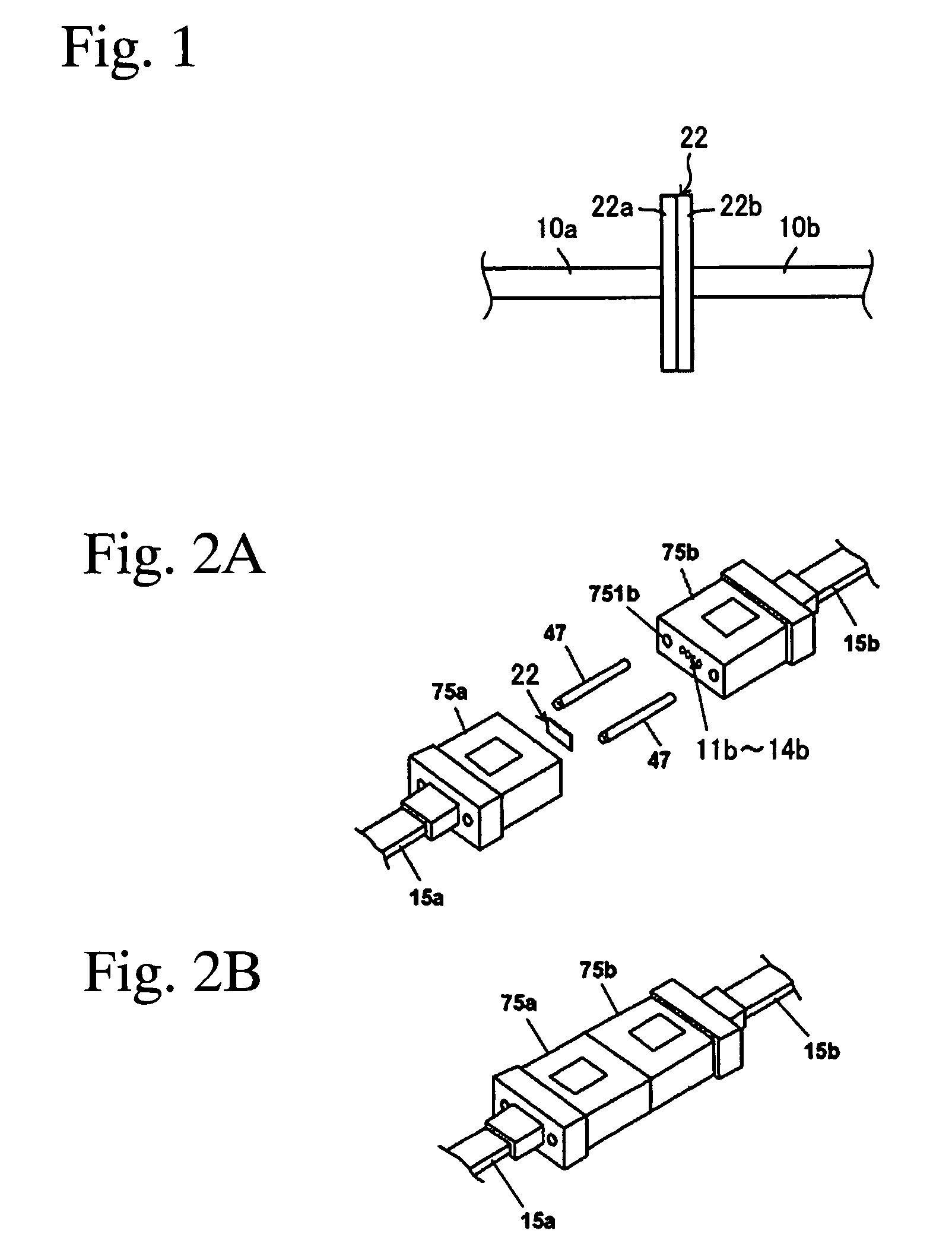
[0036]The first embodiment is explained with reference to FIG. 1.

[0037]FIG. 1 is a side view showing the optical connecting structure of the first embodiment in which the adhesive connecting member of the present invention is used.

[0038]Reference numerals 10a and 10b correspond to optical fibers, reference numeral 22 corresponds to a sheet-shaped adhesive connecting member, reference numeral 22a corresponds to a strongly adhesive face, and reference numeral 22b corresponds to a weakly adhesive face.

[0039]The sheet-shaped adhesive connecting member 22 has the strongly adhesive face 22a and the weakly adhesive face 22b. It is possible that the stron...

second embodiment

(2) Second Embodiment

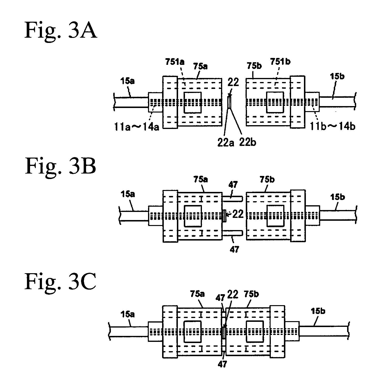
[0074]Next, the second embodiment is explained with reference to FIGS. 2 and 3.

[0075]FIG. 2 is a perspective view showing the optical connecting structure of the second embodiment using the adhesive connecting member of the present invention.

[0076]Reference numerals 11a to 14a and 11b to 14b correspond to optical fibers, reference numerals 15a and 15b correspond to an optical fiber tape core wire having four cores, reference numeral 47 corresponds to a guide pin, reference numerals 75a and 75b correspond to MT connectors, and reference numerals 751a and 751b correspond to insertion holes for guide pins.

[0077]In FIG. 2, the sheet-shaped adhesive connecting member 22 intervenes between the connection end surfaces of the MT connectors 75a and 75b.

[0078]As shown in FIG. 2A, the two MT connectors 75a and 75b are aligned by the guide pin 47 and face each other via the sheet-shaped adhesive connecting member 22. Thus, the optical fibers are optically connected as show...

third embodiment

(1) Third Embodiment

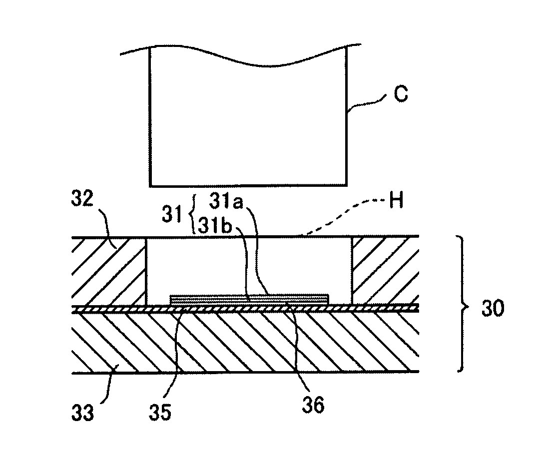
[0095]The jig for attaching the adhesive connecting member of the third embodiment of the present invention is explained with reference to FIGS. 4 and 5.

[0096]FIG. 4 is a diagram showing the jig for attaching the adhesive connecting member of the third embodiment of the present invention, FIG. 4A is a plane view, FIG. 4B is a cross sectional view along the line B-B, FIG. 4C is a perspective view, and FIG. 5 is a magnified cross sectional view along the line A-A.

[0097]Reference numeral 30 corresponds to a tabular member which forms the jig for attaching the adhesive connecting member of the third embodiment, reference numeral 31 corresponds to an adhesive connecting member, reference numeral 31a corresponds to a strongly adhesive layer, reference numeral 31b corresponds to a weakly adhesive layer, reference numeral 32 corresponds to a board having holes which forms the tabular member, reference numeral 33 corresponds to a substrate board which forms the tabular me...


PUM

PropertyMeasurementUnit
refractive indexaaaaaaaaaa
optical transmittanceaaaaaaaaaa

Abstract

An adhesive connecting member and an optical connecting structure using the member, in which connection loss can be reduced and handling is facilitated, are provided. The adhesive connecting member optically connects an optical transmission medium and another optical transmission medium or an optical part by being intervened therebetween, and the member has a strongly adhesive face contacting the optical transmission medium and a weakly adhesive face contacting the other optical transmission medium or optical part. In addition, by this adhesive connecting member, the optical transmission medium and the other transmission medium or optical part can be optically connected.

Description

TECHNICAL FIELD[0001]The present invention relates to an adhesive connecting member, to an optical connecting structure using the member, and to a jig for attaching the adhesive connecting member.BACKGROUND ART[0002]Transmission efficiency of an optical transmission path using optical fiber is greatly affected by connection loss at an optically connected part, such as between plural optical fibers or between an optical fiber and another optical part such as optical semiconductor device. As a cause of the connection loss at these connecting parts, one concerning aligning of optical fibers, such as mismatched axes, an inclined axis, or a gap between the end surface of optical fibers may be mentioned, and one concerning an end surface of an optical fiber such as an inclined surface, surface roughness, or surface waving can be mentioned.[0003]To eliminate these causes efficiently, there is a method in which a connecting device is made to have a complicated structure and high precision, ...

Claims


Application Information

Patent Timeline
Patent Type & Authority Patents(United States)
IPC IPC(8): B32B3/10G03D15/04B31F5/00B65H69/02B29C65/00
CPCG02B6/382G02B6/255Y10T428/24942Y10T428/24331G02B6/3885G02B6/40
Inventor HASHIMOTO, NOBUHIROSUZUKI, MASAYOSHIFURUE, TOMOKISUKEGAWA, KEN
Owner TOMOEGAWA CO LTD
Why Eureka
Try Eureka