
Electronic member and rotary electronic component

A technology for electronic components and electronic devices, applied in electrical components, circuits, electrical switches, etc., can solve the problems of decreased illuminance, less light, diffuse reflection of light, etc., and achieve the effect of improving illuminance and reducing light loss

Inactive Publication Date: 2006-09-20
PANASONIC CORP
View PDF1 Cites 13 Cited by
  • Summary
  • Abstract
  • Description
  • Claims
  • Application Information

AI Technical Summary

Problems solved by technology

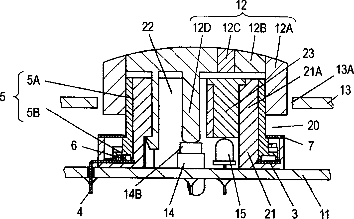
[0010] However, in such an illuminated rotary encoder that is an electronic component including a conventional rotary electronic device, the light guide portion 12C of the operation knob 12 is arranged above the hollow hole 2 formed by the cylindrical portion 1A. , and is arranged at a position away from the LED 15, so there may be such a problem: In order to make the light guide 12C in a bright lighting state, it is necessary to use a high-brightness LED 15, and the price is likely to become high.
In addition, there may be a problem that light is diffusely reflected in the space between the LED 15 mounted on the wiring board 11 and the operation knob 15, and the amount of light reaching the light guide portion 12C of the operation knob 12 decreases, resulting in a decrease in illuminance.

Method used


Image

  • Electronic member and rotary electronic component
  • Electronic member and rotary electronic component
  • Electronic member and rotary electronic component

Examples


no. 1 Embodiment

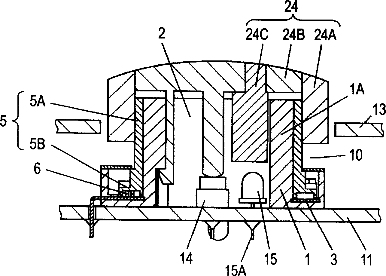
[0025] figure 1 It is a cross-sectional view showing the structure of an electronic component including a rotary electronic device according to the first embodiment of the present invention. First, the structure of the electronic components including the rotary encoder 20 which is a rotary electronic device of this embodiment in the figure will be described.

[0026] In this figure, case 21 is made of insulating resin, has a substantially annular shape with an upper opening, a substantially annular inner peripheral wall portion is cylindrical portion 21A, and hollow hole 22 is formed inside. A fixed contact 3 is disposed on the inner bottom surface of the opening, and a terminal 4 connected to the fixed contact 3 extends out of the shell 21 . In the operation shaft 5, the inner surface of the substantially cylindrical operation portion 5A is rotatably fitted to the outer surface of the cylindrical portion 21A, and the sliding contact 6 fixed on the lower surface of the flang...

no. 2 Embodiment

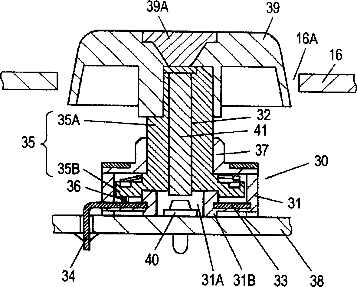
[0040] image 3 It is a cross-sectional view showing the structure of an electronic component including a rotary encoder, which is a rotary electronic device, according to a second embodiment of the present invention. In addition, parts having the same configuration as those of the first embodiment are given the same reference numerals, and detailed description thereof will be omitted. In this figure, first, the configuration of electronic components including a rotary encoder 30 which is a rotary electronic device of the present embodiment will be described.

[0041] In this figure, the shell 31 is roughly box-shaped with an upper opening, and a middle hole 31A penetrating up and down is provided at the center of the inner bottom surface of the opening, and it has a substantially cylindrical shape protruding from the lower surface around the middle hole 31A. Cylindrical protrusion 31B. Fixed contacts 33 formed in a predetermined manner are arranged on the bottom surface of ...


PUM


Abstract

An electronic member capable of reducing a loss of light until reaching the end of an operation shaft and enhancing the illumination intensity at the end of the operation shaft, and a rotary electronic component constituting the electronic member. The electronic member includes a rotary electronic component having a hollow hole penetrating in a direction of a shaft, a wiring board on which the rotary electronic component is mounted, an illuminating device mounted on the wiring board at one end of the hollow hole, and a light guide body being inserted in the hollow hole and guiding light emitted from the illuminating device to another end of the hollow hole.

Description

technical field [0001] The present invention relates to an electronic component with illumination used in the operation part of various electronic devices and a rotary electronic device constituting the electronic component. Background technique [0002] In recent years, various electronic devices such as AV equipment have been miniaturized and lowered in height, and installation methods for illuminating operation knobs from the inside have also increased, and the illuminated state is also required to be bright and easy to recognize. Taking a rotary encoder as an example, conventional electronic components with lighting used in these electronic devices and rotary electronic devices constituting the electronic components will be described. [0003] Figure 5 It is a sectional view showing the structure of a conventional electronic component including a rotary electronic device. First, the configuration of electronic components including a rotary e...

Claims


Application Information

Patent Timeline
IPC IPC(8): H01H19/00H01H9/18
CPCH05K5/0017H01H25/065H01H2219/062H01H19/025
Inventor 西本巧菅原淳
Owner PANASONIC CORP
Learn More