

Video Display Device, Head-Mounted Display and Head-up Display
- Summary
- Abstract
- Description
- Claims
- Application Information
AI Technical Summary
Benefits of technology
Problems solved by technology
Method used
Image

Examples
embodiment 1
[0053]An embodiment of the present invention will be described below with reference to the accompanying drawings.
[0054](Video Display Device)
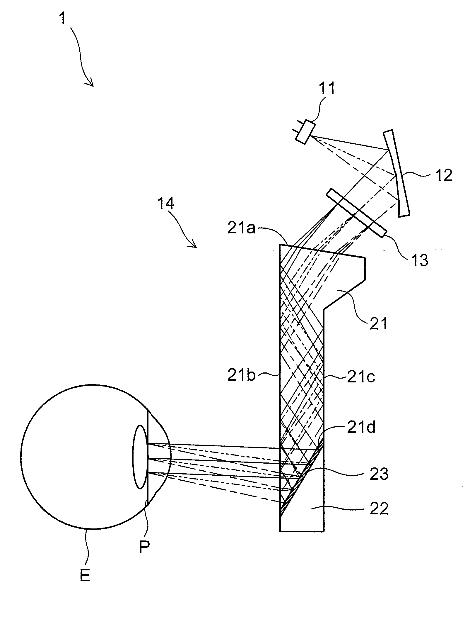
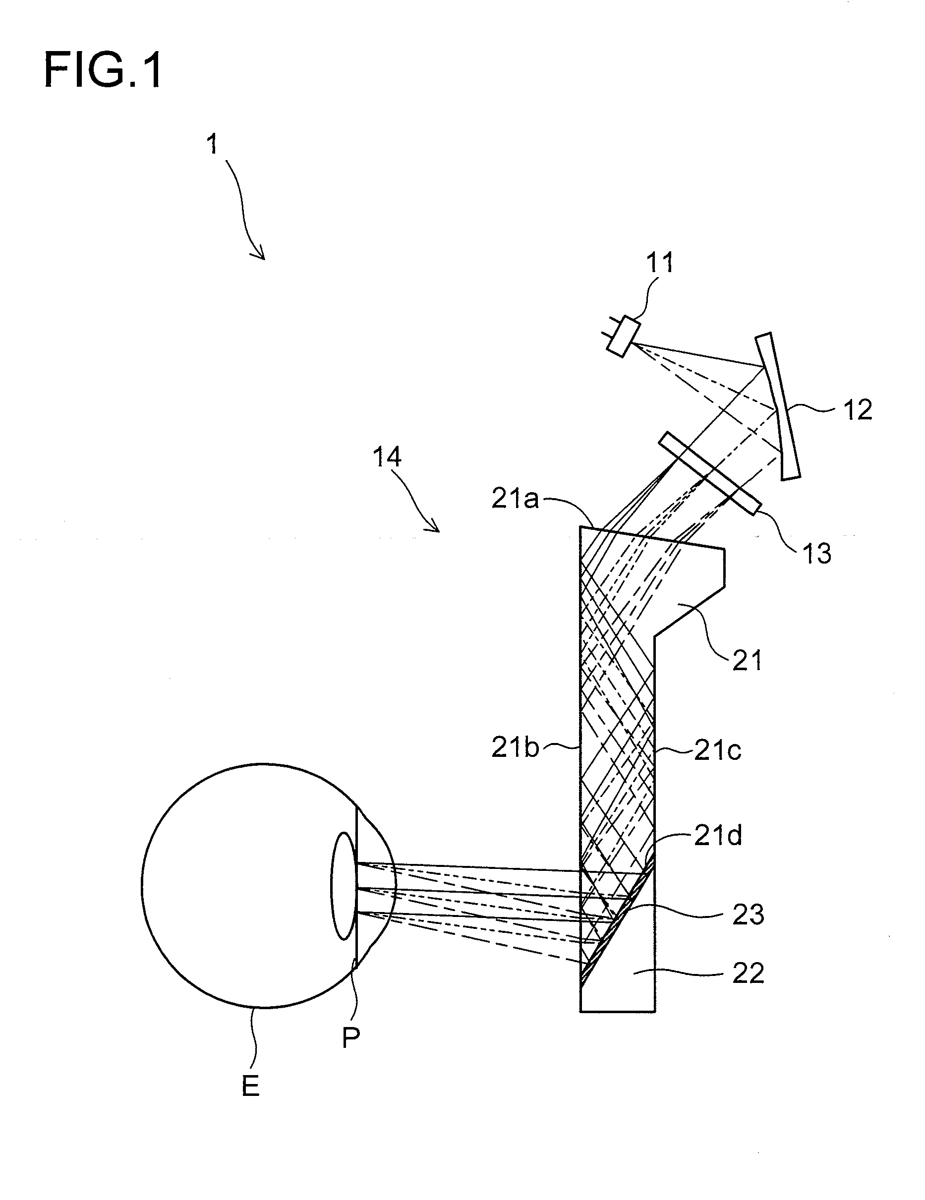
[0055]FIG. 1 is a sectional view showing an outline of the configuration of a video display device 1 according to this embodiment. The video display device 1 includes a light source 11, an illumination optical system 12, a display element 13, and an eyepiece optical system 14.
[0056]The light source 11 illuminates the display element 13, has at least one light emission peak, and emits light with a wavelength width including one light emission peak.
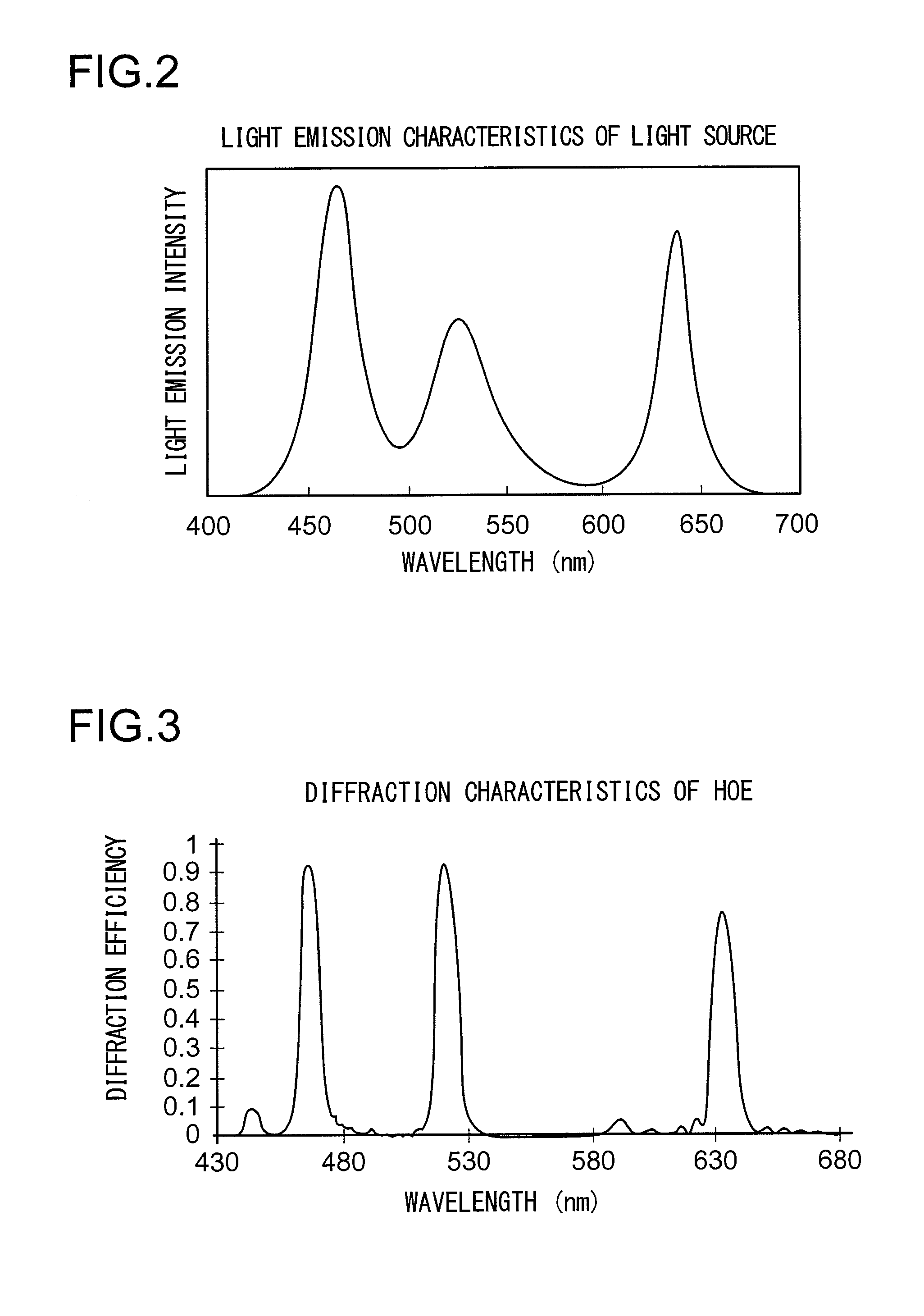
[0057]FIG. 2 shows the light emission characteristics of the light source 11 in this embodiment. In this embodiment, the light source 11 emits light having light emission peaks in three wavelength bands of blue (B), green (G), and red (R). Specifically, the light source 11 is composed of an RGB integrated LED that emits light in three wavelength bands of, for example, 462±12 nm (B light), 525±17 nm=(G ...
embodiment 2
[0110]Another embodiment of the present invention will be described below with reference to the accompanying drawings. For convenience' sake, such components as find their counterparts in Embodiment 1 are identified by common reference signs, and no overlapping description will be repeated.
[0111]FIG. 9 is a sectional view showing an outline of the configuration of a video display device 1 according to this embodiment. FIG. 10 is a perspective view of an eyepiece optical system 14 in the video display device 1. The video display device 1 according to this embodiment differs from that of Embodiment 1 in that an HOE surface 23a having an optical power equivalent to a free-form-curved concave mirror is divided into a plurality of flat faces in two directions.
[0112]Specifically, the HOE surface 23a is composed of a composite surface divided into nine flat faces (a first to a ninth flat face 31 to 39) resulting from three-part division in each of the horizontal and up / down directions. The...
embodiment 3
[0116]Yet another embodiment of the present invention will now be described with reference to the accompanying drawings. For convenience' sake, such components as find their counterparts in Embodiments 1 and 2 are identified by common reference signs, and no overlapping description will be repeated.
[0117]FIG. 11 is a sectional view showing an outline of the configuration of a video display device 1 according to this embodiment. In FIG. 11, for convenience' sake, the light source and the illumination optical system are omitted. The video display device 1 according to this embodiment is a see-through video display device that has a display element 13 arranged by the side of the observer's face. That is, an HOE 23 is arranged in front of the observer's eye; it, on one hand, diffraction-reflects image light traveling in the horizontal direction from beside the observer's face to direct it to the observer's pupil and, on the other hand, transmits light from the outside world to direct it...
PUM
 Abstract
Description
Claims
Application Information