Single servo pump control electro-hydraulic bending machine

A bending machine and servo pump technology, which is applied in the field of bending machines, can solve the problems of thin plates and fast clamping, and achieve the effect of improving safety and stability, avoiding the risk of pinching hands, and ensuring safety.

Active Publication Date: 2021-07-23
NANJING SHENGDA HEAVY IND MACHINERY
7 Cites 0 Cited by

AI-Extracted Technical Summary

Problems solved by technology

[0005] The purpose of the present invention is to provide a single-servo pump-controlled electro-hydraulic bending ...

Method used

Further, sound and light alarm is installed on the body 11, quick clamp 13 frontal walls are positioned at the front side of upper mold 14 frontal walls, upper mold 14 and lower mold 16 are on the same vertical line, strengthen bending machine body 1 The reminder effect to the user reduces the probability of production safety accidents and ensures the practicability of the bending machine body 1 .
Further, the bottom of pressing plate 28 exposes the bottom surface of fixed block 21 through movable groove 25, the bottom of pressing plate 28 is positioned at the front side of fixed block 21 front, the front of pressing plate 28 is provided with cushion, is convenient to finger and pressing plate 28 contact to ensure the protection of the pressing plate 28 to fingers and improve the safety of the bending machine body 1 .
Further, the front end of the pressure sensor 29 is positioned directly below the movable shaft 26, the rear side wall of the movable groove 25 is provided with a groove, the tail end of the first spring 210 is fixedly connected with the inwall of the groove, and the pressure sensor 29 is located at Inside the groove, when the pressing plate 28 is perpendicular to the movable shaft 26, it can be in contact with the pressure sensor 29, so as to provide a surplus space for the user to withdraw his hand, so as to prevent the rotation of the pressing plate 28 from being ...

Abstract

The invention relates to the technical field of bending machines, in particular to a single servo pump control electro-hydraulic bending machine. The bending machine comprises a bending machine body, the bending machine body comprises a machine body, a movable plate is movably installed at the upper end of the front face of the machine body, a quick clamp is fixedly connected to the bottom end of the movable plate, and an upper die is fixedly connected to the bottom face of the quick clamp; and a fixing frame is fixedly connected to the lower end of the front face of the machine body, a lower die is fixedly connected to the top face of the fixing frame, a support is movably connected to the lower side of the fixing frame, a central controller is movably connected to the right side face of the machine body, and a sliding groove is formed in the upper end of the front face of the machine body. When the bending machine is used, a pressing plate makes contact with the fingers of a user to prompt the user to rapidly retract the hand, meanwhile, through sound and light alarming, the user is rapidly awakened from a distraction state, the user is warned to rapidly retract the hand, and the reaction time is provided for the user, so that the risk of clamping the hand is avoided, the safety of the user is guaranteed, and the safety and stability of the bending machine body are improved.

Application Domain

Shaping toolsShaping safety devices

Technology Topic

Press brakeControl engineering +2

Image

  • Single servo pump control electro-hydraulic bending machine
  • Single servo pump control electro-hydraulic bending machine
  • Single servo pump control electro-hydraulic bending machine

Examples

  • Experimental program(1)

Example Embodiment

[0031] The following will clearly and completely describe the technical solutions in the embodiments of the present invention with reference to the accompanying drawings in the embodiments of the present invention. Obviously, the described embodiments are only some, not all, embodiments of the present invention. Based on the embodiments of the present invention, all other embodiments obtained by persons of ordinary skill in the art without making creative efforts belong to the protection scope of the present invention.
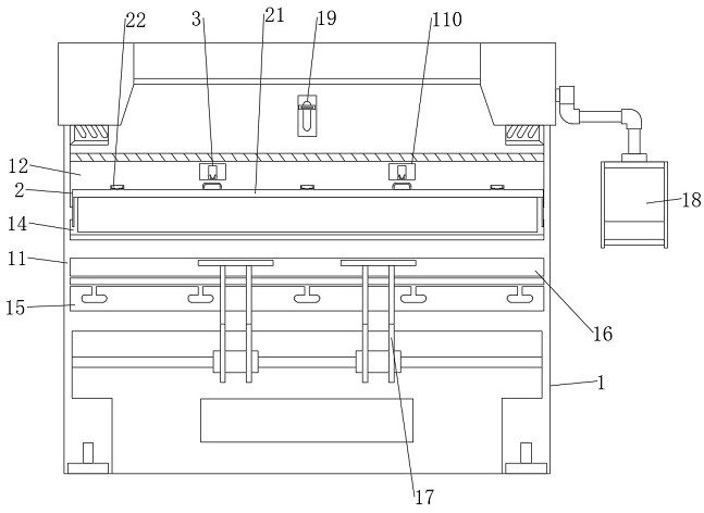
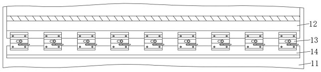
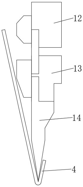
[0032] see Figure 1-8 , an embodiment provided by the present invention: a single servo pump controlled electro-hydraulic bending machine, including a bending machine body 1, the bending machine body 1 includes a body 11, and a movable plate 12 is movably installed on the upper end of the front of the body 11, The bottom of movable plate 12 is fixedly connected with fast clamp 13, and the bottom surface of quick clamp 13 is fixedly connected with upper mold 14, and the lower end of body 11 front is fixedly connected with fixed frame 15, and the top surface of fixed frame 15 is fixedly connected with lower mold 16, The lower side of fixed mount 15 is movably connected with support 17, and the right side of body 11 is movably connected with central controller 18, and the upper end of body 11 front is provided with chute 19, and the downside of chute 19 is provided with draw-in groove 110, and the body The inside of 11 is fixedly connected to the limit block 111, the front of the bending machine body 1 is movably connected to the protective structure 2, the protective structure 2 includes a fixed block 21, the front lower end of the movable plate 12 is movably connected to the fixed block 21, and the top of the fixed block 21 The surface is fixedly connected with hinge 22, the side of hinge 22 is fixedly welded with snap ring 23, the two ends of the bottom surface of fixed block 21 are fixedly connected with limiting plate 24, and the bottom surface of fixed block 21 is provided with movable groove 25, and the inside of movable groove 25 A movable shaft 26 is movably connected, the two ends of the movable shaft 26 are fixedly connected with a first return spring 27, the bottom surface of the movable shaft 26 is fixedly connected with a pressing plate 28, and the rear side of the pressing plate 28 is fixedly connected with a pressure sensor 29, the back side of the pressure sensor 29 A first spring 210 is fixedly connected, and a fixed structure 3 is installed inside the bending machine body 1 , and the fixed structure 3 includes a fixed rod 31 .
[0033]Further, the inside of the body 11 is movably connected with a fixed rod 31, the top of the fixed rod 31 is fixedly welded with a handle 32, the middle part of the fixed rod 31 is fixedly welded with a fixed column 33, and the bottom surface of the fixed column 33 is fixedly connected with a second spring 34, The bottom end of the fixed rod 31 is fixedly welded with a connecting block 35, the top surface of the connecting block 35 is movably connected with a clamping plate 36, and the inside of the bending machine body 1 is movably connected with a thin plate 4, which is convenient for fixing the turning angle of the fixed block 21, avoiding When the quick clamp 13 is operated, the pressing plate 28 will cause obstruction, and one hand needs to be freed to fix the fixing block 21, which improves the practicability of the bending machine body 1 .
[0034] Further, an audible and visual alarm is installed on the body 11, the front wall of the quick clip 13 is located on the front side of the front wall of the upper die 14, and the upper die 14 and the lower die 16 are on the same vertical line, so as to enhance the protection of the bending machine body 1 to the user. The reminder effect reduces the probability of production safety accidents and ensures the practicability of the main body 1 of the bending machine.
[0035] Further, the upper end of the hinge 22 is fixedly connected to the front wall of the movable plate 12, the fixed block 21 is located between the draw groove 110 and the upper mold 14, the length of the fixed block 21 is equal to the length of the movable plate 12, and the snap ring 23 is inverted. "U" shape structure, the snap ring 23 is positioned at the front side of the slot 110, so that the fixed block 21 can rotate on the movable plate 12, and at the same time, the snap ring 23 can be inserted into the inside of the slot 110, which is convenient for fixing the block 21. The position is fixed.
[0036] Further, the bottom of the limiting plate 24 is in contact with the front side wall of the upper mold 14, the cross section of the movable groove 25 is triangular, and the two ends of the movable shaft 26 are movably connected with the two side walls of the movable groove 25, and the first return spring The top of 27 is fixedly connected with the inner wall of movable groove 25, provides the position for the installation of movable shaft 26, makes the active force of finger to pressing plate 28 can produce reaction force to finger, to prompt the user to draw back.
[0037] Further, the bottom of the pressing plate 28 exposes the bottom surface of the fixed block 21 through the movable groove 25, the bottom of the pressing plate 28 is positioned at the front side of the front of the fixed block 21, and the front of the pressing plate 28 is provided with a cushion, which is convenient for fingers to contact with the pressing plate 28, ensuring The protection of the pressing plate 28 to fingers improves the safety of the bending machine body 1 .
[0038] Further, the front end of the pressure sensor 29 is located directly below the movable shaft 26, the rear side wall of the movable groove 25 is provided with a groove, the tail end of the first spring 210 is fixedly connected with the inner wall of the groove, and the pressure sensor 29 is located at the bottom of the groove. Inside, when the pressing plate 28 is perpendicular to the movable shaft 26, it can be in contact with the pressure sensor 29, so as to provide a surplus space for the user to withdraw his hand, and avoid the rotation of the pressing plate 28 from being blocked, causing the fingers to be squeezed.
[0039] Further, the top of the fixed rod 31 exposes the front of the body 11 through the chute 19, the handle 32 is located on the front of the body 11, the second spring 34 is sleeved on the outside of the middle part of the fixed rod 31, and the bottom of the second spring 34 is in contact with the stop. The top surface of the block 111 is fixedly connected, and the fixed rod 31 is a "J"-shaped structure, which is convenient for the user to pull the handle 32 to control the lifting of the fixed rod 31 and provide power for the reset of the fixed rod 31.
[0040] Further, the top of the connection block 35 is exposed from the bottom surface of the draw-in groove 110, and the front side of the top of the connection block 35 is fixedly equipped with a projection, and the clamping plate 36 is positioned at the rear side of the projection, so that the front of the clamping plate 36 can be in contact with the projection , to prevent the clamping plate 36 from rotating forward, so that the clamping plate 36 cannot fix the snap ring 23 inside the clamping groove 110 .
[0041] Further, a second return spring is provided at the connection between the clamping plate 36 and the connecting block 35, the width of the clamping plate 36 is smaller than the inner width of the snap ring 23, and the height of the clamping plate 36 is equal to the height of the clamping groove 110, which is the height of the clamping plate 36. The power is provided by the reset, so that the clamping plate 36 can be clamped into the inside of the snap ring 23, so as to fix the position of the snap ring 23.
[0042] Working principle: when in use, the user needs to hold the front end of the thin plate 4, and pass the rear end of the thin plate 4 between the upper mold 14 and the lower mold 16, and then the movable plate 12 will move downwards, bringing the upper mold 14 Close to the thin plate 4, then the upper mold 14 will bend the thin plate 4, and the front and rear ends of the thin plate 4 will rise upwards, and bring the user's fingers closer to the quick clamp 13, and then the user's fingers will touch the bottom of the pressing plate 28 Contact, and as the movable plate 12 continues to move, the tilting angle of the thin plate 4 continues to increase, and the fingers will squeeze the pressure plate 28 driven by the thin plate 4, so that the pressure plate 28 rotates inside the movable groove 25 and drives the movable shaft. 26 rotates, then the first return spring 27 will be deformed under the drive of the movable shaft 26, and generate a restoring force, and then generate a slight pressure on the finger to remind the user to retract the finger in time to avoid being caught by the quick clip 13 The risk of pinching, to ensure the safety of users.
[0043] When the user did not withdraw his hand due to the pressure on the finger, the finger would always be close to the quick clamp 13 along with the tilting of the front end of the thin plate 4. When the pressure plate 28 was perpendicular to the fixed block 21, the rear side of the pressure plate 28 would be in contact with the pressure sensor 29. The front end contacts, and then the pressure sensor 29 will send out an electrical signal. After the central controller 18 receives the electrical signal, it will activate the sound and light alarm. Ensure the safety of users, further improve the safety of the bending machine body 1, and at the same time, when the finger is off the thin plate 4, the sound and light alarm will still operate, which can improve the user's concentration, ensure production quality and efficiency, and avoid mental problems slack, and lead to production safety accidents.
[0044] When the upper die 14 needs to be replaced, the pressing plate 28 can be pulled so that the front of the pressing plate 28 contacts the side wall of the movable groove 25, and then the pressing plate 28 will drive the fixed block 21 to rotate around the hinge 22, and the snap ring 23 will perform a circular motion at the same time. Make snap ring 23 insert the inside of draw-in groove 110, then snap ring 23 can contact with the front of clamp plate 36, and push clamp plate 36 to turn backward, when snap ring 23 is installed in place in the inside of draw-in groove 110, clamp plate The second back-moving spring on 36 can recover, and drives clamping plate 36 to snap into the inboard of clasp 23, realizes fixing to the fixing of fixed block 21 turning angles, avoids when operating quick clip 13, and pressing plate 28 can cause blocking, and avoids needing a Fixing the fixed block 21 with only one hand improves the practicability of the bending machine body 1. After the replacement is completed, the handle 32 can be pulled downward, and the handle 32 will move downward with the fixed rod 31, and the fixed column 33 will squeeze the first The second spring 34 makes the second spring 34 contract, and the fixed rod 31 will move downward with the connecting block 35 at the same time, and then the clamping plate 36 will retract into the inside of the body 11, so that the clamping plate 36 is released from fixing the snap ring 23, and then The flipping of the fixing block 21 can cover the quick clip 13 again, which further improves the practicability of the bending machine body 1 .
[0045] It will be apparent to those skilled in the art that the invention is not limited to the details of the above-described exemplary embodiments, but that the invention can be embodied in other specific forms without departing from the spirit or essential characteristics of the invention. Accordingly, the embodiments should be regarded in all points of view as exemplary and not restrictive, the scope of the invention being defined by the appended claims rather than the foregoing description, and it is therefore intended that the scope of the invention be defined by the appended claims rather than by the foregoing description. All changes within the meaning and range of equivalents of the elements are embraced in the present invention. Any reference sign in a claim should not be construed as limiting the claim concerned.

PUM

no PUM

Description & Claims & Application Information

We can also present the details of the Description, Claims and Application information to help users get a comprehensive understanding of the technical details of the patent, such as background art, summary of invention, brief description of drawings, description of embodiments, and other original content. On the other hand, users can also determine the specific scope of protection of the technology through the list of claims; as well as understand the changes in the life cycle of the technology with the presentation of the patent timeline. Login to view more.

Similar technology patents

Self-limiting electronic gear shifter

ActiveCN101922547Aensure safetyIncreased front space and operator comfort
Owner:HANGCHA GRP

Parking braking control device and method

InactiveCN103496360Aprevent movementensure safety
Owner:GREAT WALL MOTOR CO LTD

Classification and recommendation of technical efficacy words

Why Eureka
Try Eureka