Single crystal clamp for loop wire and single wire cutting machine and use method

A cutting machine and single crystal technology, which is used in the manufacture of tools, fine work devices, work accessories, etc., can solve the problems of hand-holding being easily caught, reducing work efficiency, increasing labor costs, etc. Risks, eliminate potential safety hazards, and save labor costs

Pending Publication Date: 2022-04-12
CHINA ELECTRONICS TECH GRP NO 46 RES INST
View PDF0 Cites 0 Cited by
  • Summary
  • Abstract
  • Description
  • Claims
  • Application Information

AI Technical Summary

Problems solved by technology

[0004] One is to increase the labor cost, because one person cannot complete it, and two people must cooperate with the operation at the same time;
[0005] The second is to reduce work efficiency, because the wooden block is not fixed, it is easy to move during the tightening process of the clamp arm, which affects the effect of clamping, and rework is required at this time;
[0006] The third is that there are certain potential safety hazards in this method, and the hand-holding person is easy to be caught when the clamping arm is tightened;
[0007] Fourth, it is impossible to cut the test pieces of 6-inch and 4-inch small-sized single crystals. If there is a test piece that needs to be sliced, you can only use the TS23 internal circular machine to stick the stick to the slice. In this way, you need to use AB glue to stick the crystal stick to the graphite 2 hours in advance. Put it on the support and let it dry, then fix the graphite support on the top of the TS23 internal circular machine for slicing, and after the slicing is completed, you need to place the crystal rod on a high-temperature baking pan for degumming before you can remove the crystal rod from the graphite support, so that It takes about 3 hours to complete the slicing of a section of ingot

Method used


Image

  • Single crystal clamp for loop wire and single wire cutting machine and use method
  • Single crystal clamp for loop wire and single wire cutting machine and use method
  • Single crystal clamp for loop wire and single wire cutting machine and use method

Examples


Embodiment Construction

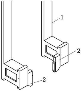
[0021] like figure 1 As shown, a single crystal clamp for circular wire and single wire cutting machine includes cutting machine clamp arm 1 and single crystal clamp. The single crystal clamp is composed of two sets of single clamps 2. Plate II 2-2 constitutes.

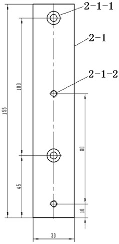
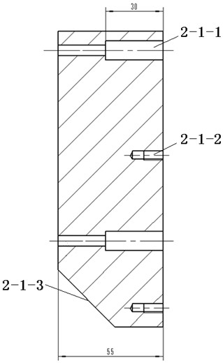
[0022] like figure 2 , image 3 As shown, the reinforcement plate I2-1 is a cuboid, and two counterbores I2-1-1 communicating with the back are arranged at intervals on the main surface of the reinforcement plate I2-1, and between the two counterbores I2-1-1 A blind hole 2-1-2 with an internal thread is respectively provided under the sink hole I2-1-1, and a slope 2-1-3 is formed between the bottom surface and the back of the support plate I2-1.

[0023] like Figure 4 , Figure 5 As shown, the reinforcing plate II2-2 is a cuboid, and two counterbores II2-2-1 communicating with the back are provided at intervals on the main surface of the reinforcing plate II2-2.

[0024] Fix a single crystal fixture on the two...


PUM


Abstract

The invention relates to a single crystal clamp for a loop wire and single wire cutting machine and a using method, and belongs to the technical field of semiconductor silicon material cutting processing, and the method comprises the following steps: stably placing a 6-inch or 4-inch single crystal on an objective table of a cutting machine, and enabling two clamping arms of the cutting machine to transversely move in opposite directions through an operation interface, the clamping plates II of the two single clamps are respectively in contact with the single crystal and clamp the single crystal; and then the two clamping arms are moved back and forth, so that the single crystal is moved to an appointed position needing to be cut, and the single crystal can be cut off. According to the invention, the slicing work of the test piece of 6-inch and 4-inch small-size single crystals is optimized, the cutting of the test piece of one section of single crystal can be completed in only 20 minutes, the operation is simple, and the working efficiency is improved.

Description

technical field [0001] The invention relates to the technical field of semiconductor silicon material cutting and processing, in particular to a single crystal clamp for a ring wire and a single wire cutting machine and a use method thereof. Background technique [0002] The single-wire and ring-wire cutting machines currently used in production are only suitable for 8-inch and above-sized single crystals, and the lateral contraction range of their clamp arms is limited, and they cannot hold small-sized single crystals, which limits their scope of use. [0003] The single-wire and ring-wire cutting machines used in the prior art can only use wooden blocks to fill between the crystal rod and the two clamp arms when cutting small-sized single crystals of 6 inches and 4 inches, and two people are required to cooperate at the same time when holding Operation, where one person holds the wooden block to fix it, and the other person performs interface operation on the machine table...

Claims


Application Information

Patent Timeline
Patent Type & Authority Applications(China)
IPC IPC(8): B28D7/04B28D7/00B28D5/04
Inventor 索开南曹志颖张伟才宋家祥李东剑国佳方继伟王东兴
Owner CHINA ELECTRONICS TECH GRP NO 46 RES INST
Why Eureka
Try Eureka