Burner and combustion device using same

A combustion device and combustion chamber technology, applied in the direction of burners, combustion methods, combustion types, etc., can solve the problems of difficult ignition of gas pipes, ignition deflagration, and affecting the maximum combustion effect of burners, so as to improve combustion effect and reduce NOx concentration Effect

Inactive Publication Date: 2021-07-23
刘翠霞
View PDF0 Cites 0 Cited by
  • Summary
  • Abstract
  • Description
  • Claims
  • Application Information

AI Technical Summary

Problems solved by technology

[0003] However, in the above scheme, there is only one gas pipe leading to the combustion chamber, which is limited by the setting of the maximum flow rate of the gas pipe, which makes the gas pipe prone to difficult ignition and ignition deflagration. If the gas pipe is directly reduced The size will affect the maximum combustion effect of the burner

Method used


Image

  • Burner and combustion device using same
  • Burner and combustion device using same
  • Burner and combustion device using same

Examples


Embodiment 1

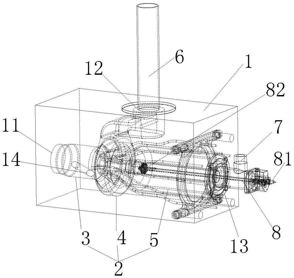
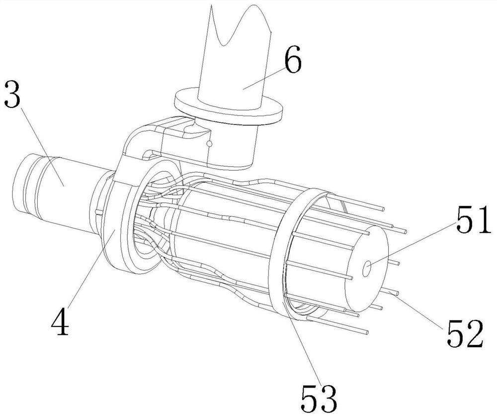
[0026] Such as figure 1 As shown, a burner is disclosed in this embodiment, which includes a body 1, and the surface of the body 1 is provided with a flame outlet 11, a gas-supporting gas inlet port 12 for communicating with the gas-supporting gas conduit 6, and several The gas inlet port 13 communicated with the gas conduit 7. The main body 1 is provided with an inner chamber main body 2. The inner chamber main body 2 includes a combustion chamber 3, an air-fuel guide chamber 4 and a gas inlet channel 5. The combustion chamber 3 communicates with the flame outlet 11, and the gas inlet channel 5 communicates with the gas The air inlet port 13 is connected, the air-fuel guiding body chamber 4 and the gas inlet channel 5 are connected to the combustion chamber 3 , and the gas-supporting gas inlet port 12 is connected to the air-fuel guiding body chamber 4 . combine figure 2 As shown, the gas inlet passage 5 includes a primary gas passage 51, an annular passage 53 and several ...

Embodiment 2

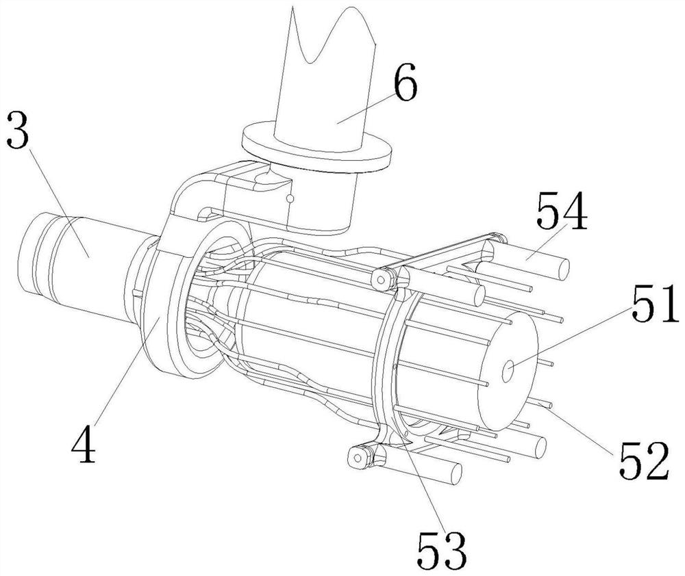
[0031] This embodiment is different from Embodiment 1 in that the gas inlet passage 5 also includes a plurality of three-stage gas passages 54, and the three-stage gas passages 54 communicate with the annular passage 53. Correspondingly, the number of gas inlet ports 13 is one The sum of the number of first-level gas passages 51, second-level gas passages 52 and third-level gas passages 54. The sum of the sectional areas of the air inlets of the four tertiary gas passages 54 is greater than the sum of the sectional areas of the air inlets of the secondary gas passages 52 .

[0032] In this embodiment, the number of three-level gas passages 54 is four, and it can also be replaced by three, five or six-level gas passages. Correspondingly, the number of gas inlet ports 13 communicating with the gas conduit 7 changes accordingly.

Embodiment 3

[0034] combine Figure 4-6 As shown, a combustion device is disclosed in this embodiment, which uses any burner in Embodiment 1 or Embodiment 2. The heat storage body 10 is provided with a space for storing exhaust gas, and the body 1 is provided with a flame outlet. One end of the air outlet 11 extends into the heat storage body 10 .


PUM


Abstract

The invention discloses a burner. The burner comprises a body, wherein a flame outlet, a combustion-supporting gas inlet connector and a gas inlet connector are arranged on the surface of the body, an inner cavity main body is arranged inside the body and comprises a combustion chamber, an air-fuel flow guide body cavity and a gas inlet channel, the combustion chamber communicates with the flame outlet, the gas inlet channel communicates with the gas inlet connector, the air-fuel flow guide body cavity and the gas inlet channel both communicate with the combustion chamber, the combustion-supporting gas inlet connector communicates with the air-fuel flow guide body cavity, the gas inlet channel comprises a first-stage gas channel and a plurality of second-stage gas channels annularly arranged on the periphery of the first-stage gas channel, and the second-stage gas channels communicate through an annular channel arranged on the periphery of the first-stage gas channel in a sleeve mode. The invention provides a burner which is provided with the gas channels with multiple flow levels, ignition is conducted through the minimum flow by the burner, then the supply amount of gas is gradually increased, and the situation that ignition is difficult or ignition deflagration occurs can be effectively avoided.

Description

technical field [0001] The invention relates to the technical field of burners, more specifically, to a burner and a combustion device for its application. Background technique [0002] In the Chinese invention patent with the publication number CN1062877241A, a low NOx flat flame high temperature resistant heat exchange burner with staged combustion technology is disclosed. , to realize the graded supply of high-temperature heat exchange air to the combustion chamber and the flat flame combustion chamber, so that part of the air and gas are mixed in the combustion chamber to form low-oxygen combustion, which can effectively reduce the flame temperature of the fuel during the initial combustion process and inhibit nitrogen oxidation The formation of pollutants greatly reduces NOx emissions. Due to the use of the heat exchanger, the heat energy of the high-temperature exhaust smoke is used to heat the combustion-supporting air to realize the secondary waste heat recovery, so...

Claims


Application Information

Patent Timeline
Patent Type & Authority Applications(China)
IPC IPC(8): F23D14/02F23D14/62F23D14/46
CPCF23D14/02F23D14/46F23D14/62
Inventor 刘翠霞
Owner 刘翠霞
Why Eureka
Try Eureka