air conditioner

An air conditioner and sensor technology, applied in the field of air conditioning, can solve the problems of increased installation man-hours, waste of man-hours, and low installation efficiency, and achieve the effects of increased installation efficiency, simple mold design, and standardized and safe wiring

Active Publication Date: 2022-05-27
QINGDAO HISENSE HITACHI AIR CONDITIONING SYST
View PDF8 Cites 0 Cited by
  • Summary
  • Abstract
  • Description
  • Claims
  • Application Information

AI Technical Summary

Problems solved by technology

[0002] At present, there are various temperature sensor brackets for air conditioners, and there are various problems. Some temperature sensor brackets are less safe. After the temperature sensor is fixed on the temperature sensor bracket, the temperature sensor is exposed and accessible to people. , does not meet the requirements of safety regulations. Usually, it is necessary to put an additional layer of insulating protective cover on the temperature sensor, but this method is costly, and the installation steps are complicated and increase the installation man-hours; some temperature sensor brackets are not set properly. The wiring of the sensor wiring is cumbersome, and other structural parts need to be assisted to meet the wiring requirements. There are many parts involved, the installation efficiency is low, and the cost is high; there are also some temperature sensor brackets that are separated, which wastes man-hours when combined. , increase cost; currently there is no temperature sensor bracket that can better solve the above problems, which makes the installation of the temperature sensor and temperature sensor bracket of the air conditioner more complicated and increases the cost of the air conditioner

Method used


Image

  • air conditioner
  • air conditioner
  • air conditioner

Examples


Embodiment Construction

[0035] Hereinafter, the present invention will be specifically described through exemplary embodiments. It should be understood, however, that elements, structures and features of one embodiment may be beneficially combined in other embodiments without further recitation.

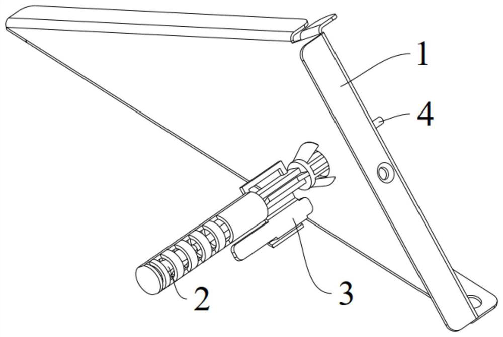
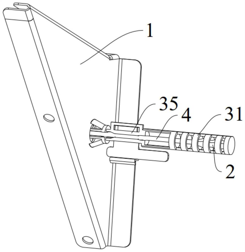
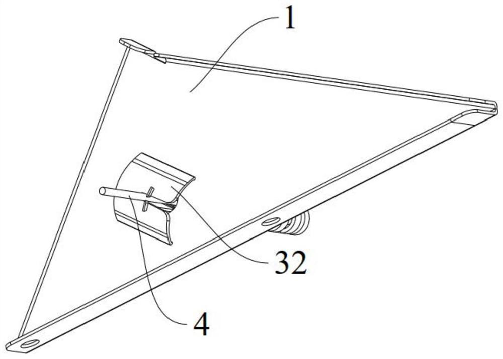
[0036] The present invention proposes an air conditioner, which is referred to below Figure 1-10 Describe the air conditioner.

[0037] The air conditioner performs a refrigeration cycle of the air conditioner by using a compressor, a condenser, an expansion valve, and an evaporator. The refrigeration cycle includes a series of processes involving compression, condensation, expansion, and evaporation, and supplies refrigerant to air that has been conditioned and heat-exchanged.

[0038] The compressor compresses the refrigerant gas in a high temperature and high pressure state and discharges the compressed refrigerant gas. The discharged refrigerant gas flows into the condenser. The condenser condenses...


PUM


Abstract

The present invention proposes an air conditioner, comprising: a casing; a fixing plate, on which a fixing hole is arranged; a temperature sensor, the end of the temperature sensor is connected with sensor wiring; a sensor bracket, including: a protective cage, arranged at one end of the sensor bracket And there is a window on it, and a temperature sensor is arranged in the protective cage; the card seat is located at the other end of the sensor bracket and its inner side is connected with the inner end of the protective cage through a connecting part; the elastic claw is located between the card seat and the protective cage Between; the sensor wires pass through the elastic claws and the card seat in turn to extend out of the sensor bracket, and the protective cage and the elastic claws pass through the fixing holes in turn to limit the fixing plate between the elastic claws and the card seat; the temperature sensor is set at In the protective cage, the temperature sensor can be effectively protected from being touched. The window is set, and the air flows into the protective cage, so that the temperature sensor can accurately sense the air temperature. Board is better connected.

Description

technical field [0001] The present invention relates to the technical field of air conditioners, and in particular, to an air conditioner. Background technique [0002] At present, there are various temperature sensor brackets for air conditioners, and there are various problems. Some temperature sensor brackets have low safety. After the temperature sensor is fixed on the temperature sensor bracket, the temperature sensor is exposed and can be touched by people. , does not meet the requirements of safety regulations, it is usually necessary to put an additional layer of insulating protective cover on the temperature sensor, but the cost of this method is high, and the installation steps are complicated and increase the installation time; some temperature sensor brackets are set unreasonably, This makes the wiring of the sensor wiring more cumbersome, and needs to assist other structural components to meet the wiring requirements, involving many parts, low installation effic...

Claims


Application Information

Patent Timeline
Patent Type & Authority Patents(China)
IPC IPC(8): F24F1/0007F24F11/89F24F13/32
CPCF24F1/0007F24F11/89F24F13/32
Inventor 葛磊磊张允峰陶友淘徐坤郇岩强董世雷
Owner QINGDAO HISENSE HITACHI AIR CONDITIONING SYST
Why Eureka
Try Eureka