Cable marker printing and threading machine

A number tube, threading machine technology, applied in electrical components, circuits, marking conductors/cables, etc., can solve problems such as inability to accurately clamp and thread wires, shaping and fixed-point output, etc., to ensure accuracy and good correction. The effect of shaping and stable conveying

Active Publication Date: 2017-02-01
GUANGZHOU CHANGLI MACHINERY EQUIP CO LTD
View PDF3 Cites 18 Cited by
  • Summary
  • Abstract
  • Description
  • Claims
  • Application Information

AI Technical Summary

Problems solved by technology

Because the number tube is a hose and naturally bends, the existing number tube printer cannot shape it and output it at a fixed point, let alone accurately clamp and penetrate the wire

Method used


Image

  • Cable marker printing and threading machine
  • Cable marker printing and threading machine
  • Cable marker printing and threading machine

Examples


Embodiment 1

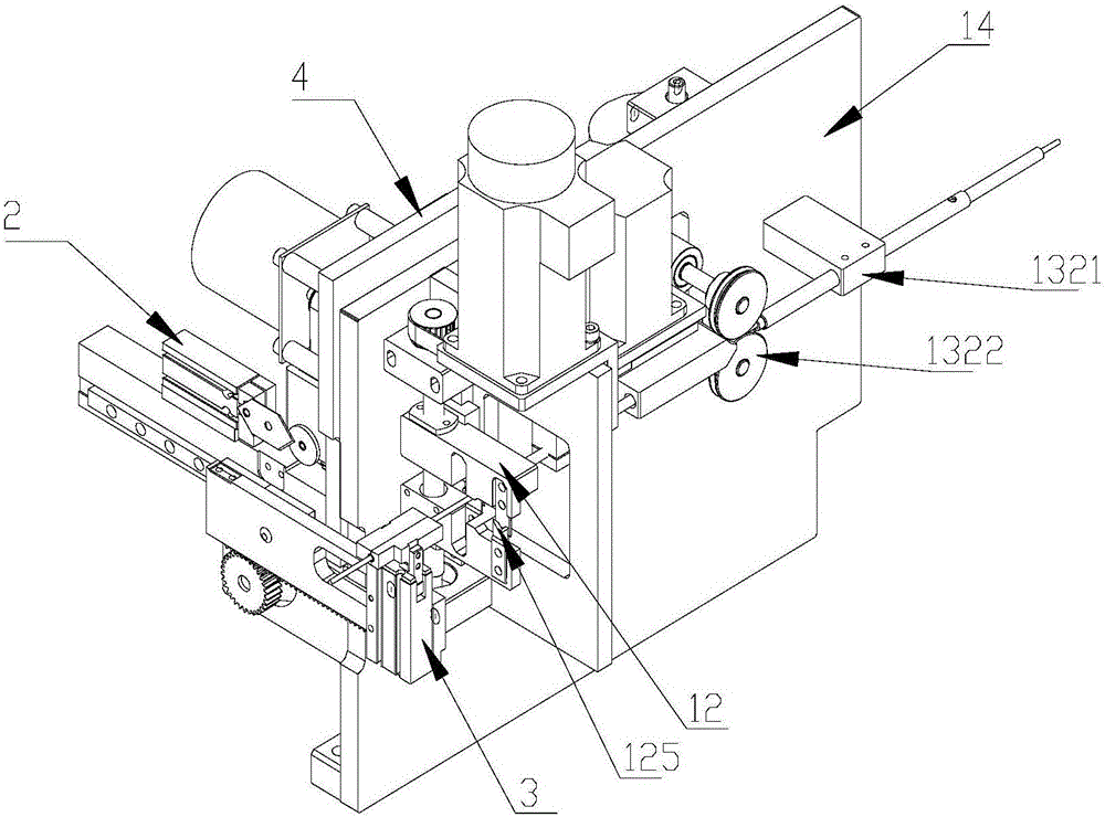
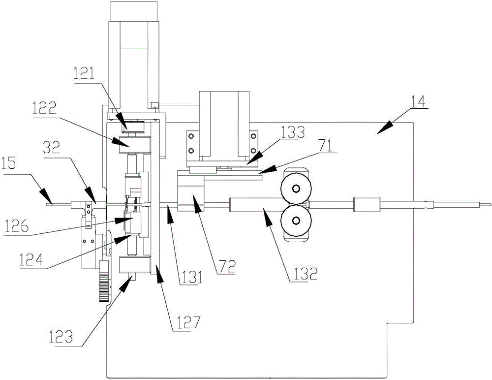
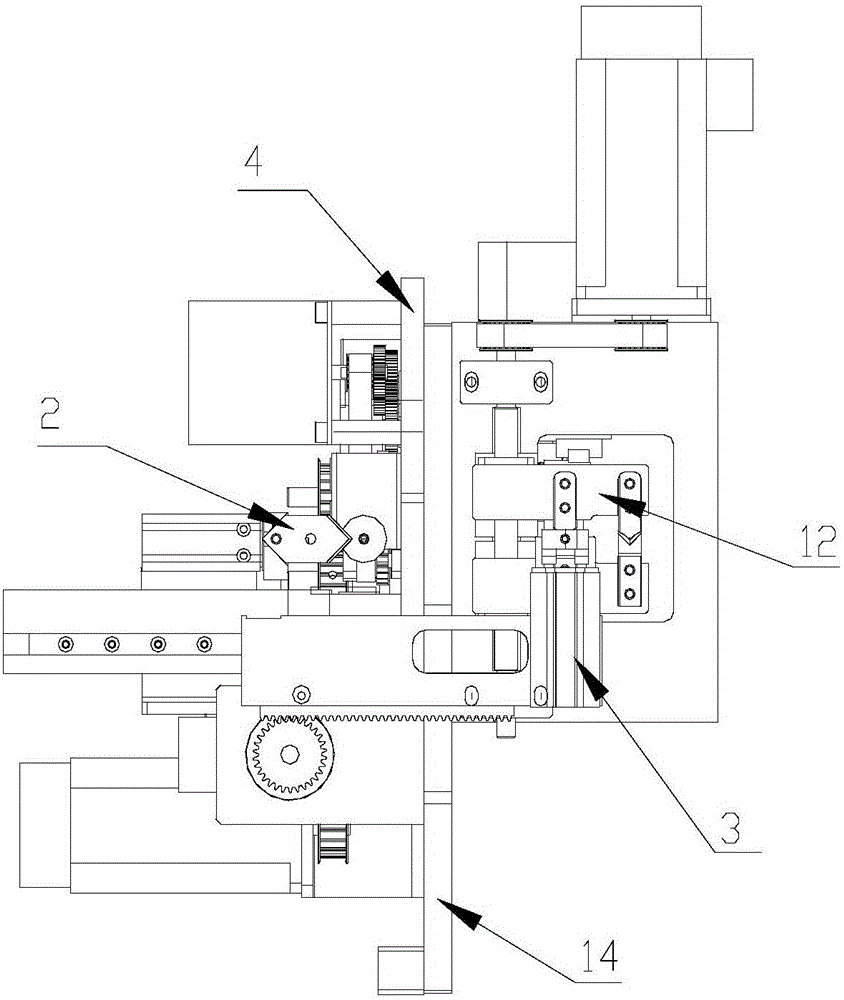
[0052] Such as Figure 1 to 6 As shown, a number tube printing and threading machine includes a printing assembly 1, a gear box assembly 9, a printing motor 10, a number tube cutting assembly 2, a clamping and moving assembly 3, a first mounting plate 14, a printing main panel 4, and a second Mounting plate 6, wire cutting assembly 12 and threading assembly 13. The printing main panel 4 is installed on the first mounting plate 14. The second mounting plate 6 is installed horizontally and vertically at the lower part of the printing main panel 4. The printing main panel 4 is installed with the printing assembly 1 and the gear box assembly 9, and the first mounting plate 14 is installed The threading assembly 13 and the wire cutting assembly 12, the numbering tube cutting assembly 2 and the clamping moving assembly 3 are installed on the second mounting plate 6. The numbering pipe cutting assembly 2 is located at the numbering tube outlet of the clamping moving assembly 3 and the ...

Embodiment 2

[0066] Such as Figure 12 to Figure 17 As shown, a number tube printing and threading machine includes a printing assembly 1, a gear box assembly 9, a printing motor 10, a number tube cutting assembly 2, a clamping and moving assembly 3, a guide pin assembly 8, a first mounting plate 14, and a printing main Panel 4, second mounting plate 6, wire cutting assembly 12 and threading assembly 13. The printing main panel 4 is installed on the first mounting plate 14, the second mounting plate 6 is installed horizontally and vertically at the lower part of the printing main panel 4. The printing main panel 4 is installed with the printing assembly 1 and the gear box assembly 9, and the first mounting plate 14 is installed The threading assembly 13 and the wire cutting assembly 12, the numbering tube cutting assembly 2 and the clamping moving assembly 3 are installed on the second mounting plate 6, and the numbering pipe cutting assembly 2 is located at the numbering tube outlet of the ...

Embodiment 3

[0074] A number tube printing and threading machine, including a printing assembly 1, a gear box assembly 9, a printing motor 10, a number tube cutting assembly 2, a clamping and moving assembly 3, a guide pin assembly 8, a first mounting plate 14, a printing main panel 4. The second mounting plate 6, the wire cutting assembly 12 and the threading assembly 13. The printing main panel 4 is installed on the first mounting plate 14, the second mounting plate 6 is installed horizontally and vertically at the lower part of the printing main panel 4. The printing main panel 4 is installed with the printing assembly 1 and the gear box assembly 9, and the first mounting plate 14 is installed The threading assembly 13 and the wire cutting assembly 12, the numbering tube cutting assembly 2 and the clamping moving assembly 3 are installed on the second mounting plate 6, and the numbering pipe cutting assembly 2 is located at the numbering tube outlet of the clamping moving assembly 3 and t...


PUM

PropertyMeasurementUnit
Shore hardnessaaaaaaaaaa

Abstract

The invention relates to a cable marker printing and threading machine. The cable marker printing and threading machine comprises a movable clamping component, a threading component, a wire cutting component, a first mounting plate and a printing main panel; the printing main panel is arranged on the first mounting plate; the threading component and the wire cutting component are arranged on the first mounting plate; the movable clamping component is arranged on the printing main panel; the threading component comprises a threading pipe, a wire feeding structure, a guiding structure, a mounting block, a moving structure and a fourth mounting plate; a wire is arranged in the threading pipe; the wire feeding structure is located behind the mounting block and comprises at least a pair of wire feeding friction wheels used for transferring the wire; the wire cutting component is located in front of the threading component and is used for cutting off the wire; the movable clamping component comprises a cable marker mould which can be opened and closed, a clamping hole is formed in the cable marker mould, and the clamping hole is coaxial with the threading pipe. The cable marker printing and threading machine solves a calibration problem of the wire penetrating the cable marker and guarantees accuracy of the wire penetrating the cable marker.

Description

Technical field [0001] The invention relates to the field of wire processing, in particular to a number tube printing and threading machine. Background technique [0002] In the electrical control, power distribution equipment, and integrated wiring industries, both ends of the wiring need to be marked to facilitate accurate installation of wires and troubleshooting. In the prior art, a number tube printer is used to print identification characters on number tubes (such as PVC sleeves, heat-shrinkable tubes), and then the number tubes are manually threaded on the wires in a one-to-one correspondence. This method is inefficient, and it is easy to mismatch the number tube and the wire. [0003] In the existing number tube printer, there is only one driving wheel that pushes the number tube, that is, the printing wheel that presses the number tube on the print head. When the number tube is printed, it is naturally pushed forward into the cutting edge for full or half cut, and then P...

Claims


Application Information

Patent Timeline
Patent Type & Authority Applications(China)
IPC IPC(8): H01B13/34
CPCH01B13/344
Inventor 夏武
Owner GUANGZHOU CHANGLI MACHINERY EQUIP CO LTD
Why Eureka
Try Eureka