
Preparation method of multi-focus diffraction element, and multi-focus diffraction element

A diffractive element and multi-focus technology, applied in the field of optical elements, can solve the problems of inconsistent peak energy intensity and full width at half maximum, inconsistent diffusion function, inconvenient processing, etc., achieve flexible and wide use scenarios, avoid alignment problems, increase focus deep effect

Active Publication Date: 2019-04-05
CHANGCHUN INST OF OPTICS FINE MECHANICS & PHYSICS CHINESE ACAD OF SCI
View PDF3 Cites 5 Cited by
  • Summary
  • Abstract
  • Description
  • Claims
  • Application Information

AI Technical Summary

Problems solved by technology

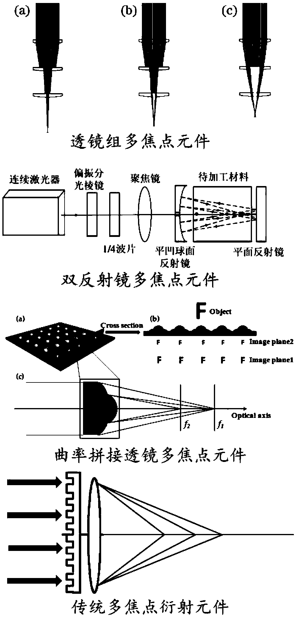
The common form of this type of optical element is: a lens group composed of multiple lenses or an optical multiple reflection system composed of two high-precision mirrors. This kind of multi-focus optical device is not only large in size, but also inconvenient to adjust the optical path. , which greatly limits its application scenarios; and the optical components in the system usually need to be made into a hollow structure, which is not easy to process
The second is to use diffractive optics to achieve multi-focus, but this traditional multi-focus diffractive element has three major disadvantages: ①The traditional multi-focus diffractive element is actually a refractive-diffractive hybrid optical device composed of two parts: a traditional convex lens and diffractive optical elements
This method also limits its functional use to a certain extent. For example, when it is used in a bionic compound eye structure, the alignment of the two optical elements becomes an urgent problem to be solved.
②Due to inherent design problems, this traditional diffractive multi-focus optical element cannot form equidistant multi-focus
③The point spread function of each focal point is inconsistent, resulting in inconsistent peak energy intensity and full width at half maximum of each focal point, thus affecting the imaging quality of each focal plane

Method used


Image

  • Preparation method of multi-focus diffraction element, and multi-focus diffraction element
  • Preparation method of multi-focus diffraction element, and multi-focus diffraction element
  • Preparation method of multi-focus diffraction element, and multi-focus diffraction element

Examples


Embodiment Construction

[0028] In the following description, specific details such as specific system structures and technologies are presented for the purpose of illustration rather than limitation, so as to thoroughly understand the embodiments of the present application. It will be apparent, however, to one skilled in the art that the present application may be practiced in other embodiments without these specific details. In other instances, detailed descriptions of well-known systems, devices, circuits, and methods are omitted so as not to obscure the description of the present application with unnecessary detail.

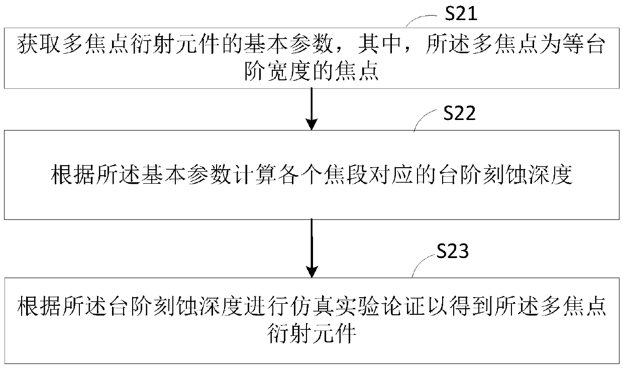
[0029] figure 2 The preparation method of the multi-focus diffraction element provided by the application is shown, and the details are as follows: the preparation method includes:

[0030] Step S21, acquiring basic parameters of the multi-focus diffraction element, wherein the multi-focus is a focus with equal step width.

[0031] In the examples provided in the present applicati...


PUM


Abstract

The invention relates to a preparation method of a multi-focus diffraction element, and the multi-focus diffraction element. The preparation method comprises the steps: basic parameters of the multi-focus diffraction element are obtained; according to the basic parameters, step etching depths corresponding to all focal lengths are calculated; and according to the step etching depths, simulation experiment demonstration is conducted to obtain the multi-focus diffraction element. According to the multi-focus diffraction element, the size of the multi-focus diffraction element is decreased, the aligning problem of a plurality of optical elements is avoided, and thus usage scenarios of the multi-focus diffraction element are more flexible and wider; and the multi-focus diffraction element cangenerate a plurality of equidistant focuses, peak energy uniformity and point spread function consistency of all the focuses can both have good results through optimization, and the multi-focus diffraction element can serve as an important light splitting element in a high-precision micro-nano processing system and has a very important effect on increasing the focal depth in certain specific imaging optical systems.

Description

technical field [0001] The present application relates to the technical field of optical elements, in particular to a method for preparing a multi-focus diffractive element and the multi-focus diffractive element. Background technique [0002] Multifocal optical elements can make a beam of parallel light converge at multiple axial focal points simultaneously. This special optical property makes multifocal optical elements widely used in various modern optical processing and imaging systems. For example, when cutting thick transparent materials with a femtosecond laser, since the cutting and separation of transparent materials with a single laser focus is greatly affected by the thickness of the material, as the thickness of the transparent material increases, the trend of the thermal cracks induced at the laser focus in the thickness direction Uncontrolled, resulting in irregular cutting cross-section, and even surface chipping, which seriously affects the physical propertie...

Claims


Application Information

Patent Timeline
Patent Type & Authority Applications(China)
IPC IPC(8): G02B5/18G02B27/00
CPCG02B5/1857G02B27/0012
Inventor 王孝坤张海东张学军薛栋林
Owner CHANGCHUN INST OF OPTICS FINE MECHANICS & PHYSICS CHINESE ACAD OF SCI
Learn More