Installation method for integrally dragging cantilever beam onto platform

An installation method and cantilever beam technology are applied in the field of cantilever beam installation in the construction of offshore platforms, which can solve the problems of closing, long construction period, impossibility of towing, difficulty in controlling the construction accuracy of cantilever beams, etc., to ensure integrity, The effect of shortening the construction period and significant economic benefits

Active Publication Date: 2012-05-30
DALIAN SHIPBUILDING IND
View PDF5 Cites 18 Cited by
  • Summary
  • Abstract
  • Description
  • Claims
  • Application Information

AI Technical Summary

Problems solved by technology

Using the above-mentioned construction technology, the integrity of the cantilever beam cannot be guaranteed when it is on the platform, the closing and construction period is long, and the construction accuracy of the cantilever beam is difficult to control
[0004] If the construction is carried out with the technology of towing after the overall construction of the cantilever beam, the main difficulty lies in that the lower track at the bow end of the cantilever beam is an upturned type, and its upturned height far exceeds the opening height of the HOLDDOWN seat
According to the normal dragging technique, the upturned track of the cantilever beam cannot pass through this structure, and the dragging cannot be implemented

Method used


Image

  • Installation method for integrally dragging cantilever beam onto platform
  • Installation method for integrally dragging cantilever beam onto platform
  • Installation method for integrally dragging cantilever beam onto platform

Examples


Embodiment Construction

[0026] Such as Figure 7 The process shown, refer to Figure 8 Illustrate the installation method of the whole cantilever beam of the present invention dragged to the platform, including the following steps:

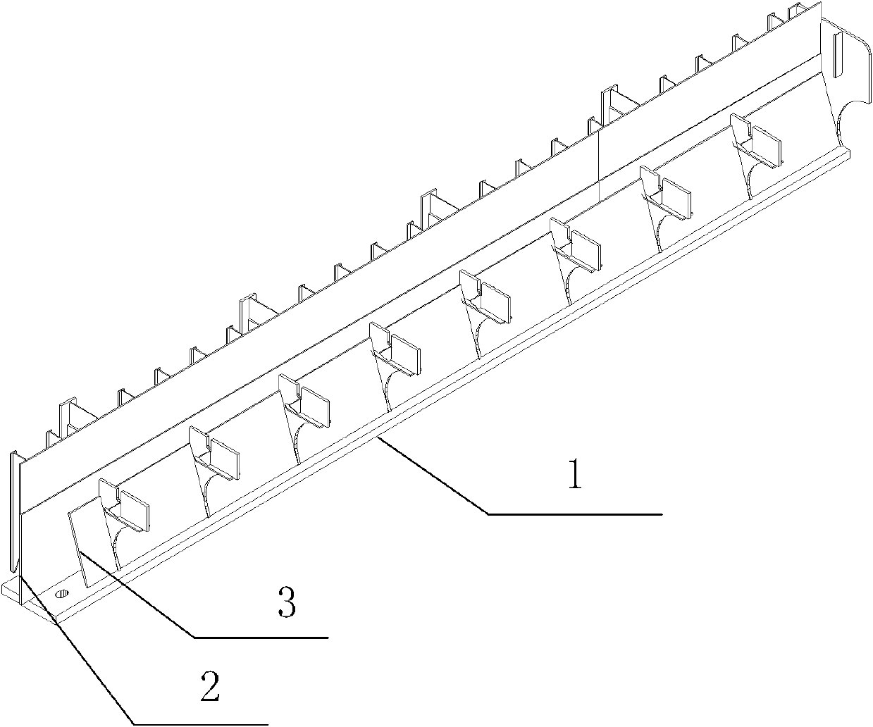
[0027] Step 1. Independently construct the upturned part of the track in the glide path at the bow end of the cantilever beam. attached figure 1 It is a cantilever beam lower track structure built separately in the open area of ​​the bow (upward warping slide track), and the structure is machined as a whole after all welding work is completed. The structure mainly includes the main structures such as the lower sliding track panel 1, the main vertical plate 2 and the V-shaped plate 3.

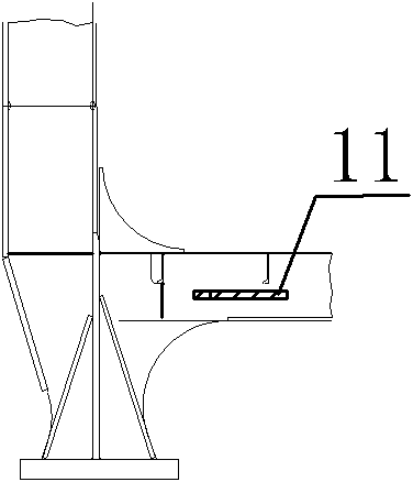
[0028] Step 2. After the cantilever beam is built as a whole on the bank, the upturned part of the track is horizontally sealed at the installation position of the cantilever beam with fixing parts. At this time, there is a gap between the upturned part of the track and the cantilever b...


PUM


Abstract

The invention discloses an installation method for integrally dragging a cantilever beam onto a platform, which comprises the following steps of: independently constructing a track at the tilted part in a lower slide way at the bow end of the cantilever beam; integrally constructing the cantilever beam, and sealing the track at the tilted part in the installation position of the cantilever beam in a horizontal mode; moving the cantilever beam onto a temporary slide way, and integrally dragging the cantilever beam onto the platform by utilizing a traction mechanism; and after the cantilever beam is dragged in place, dismantling the sealing component, lifting the track at the tilted part in the horizontal state to be in a tilted state by utilizing a lifting device, and fixing the track by welding. Through the method disclosed by the invention, the cantilever beam can be manufactured integrally on the land, and all devices are installed in place before the cantilever beam is folded, thereby greatly ensuring the construction integrality of the cantilever beam. A tilted slide track is flattened in advance before being dragged onto the platform, thereby being convenient for passing through a HOLDDOWN device. Simultaneously, the construction accuracy is convenient to control in integral construction of the cantilever beam. The dragging installation can shorten the construction cycle and is safe and reliable. The installation method disclosed by the invention has obvious economic benefit.

Description

technical field [0001] The invention relates to the field of ocean engineering, and more specifically, relates to a method for installing a cantilever beam during the construction of an ocean platform. Background technique [0002] The jack-up drilling platform designed by MSC has a special structure of the cantilever beam, and its moving mode is also very different from the cantilever beams of other design companies. The bow end of the cantilever beam lower track is upturned, and the drill floor is fixed to the main body of the cantilever beam. The whole cantilever beam can not only move longitudinally (X direction), but also move laterally (Y direction). [0003] At present, the cantilever beams built with MSC technology are all divided into 2 to 3 sections for construction, and then hoisted on the platform by a crane to close them up. Using the above-mentioned construction technology, the integrity of the cantilever beam cannot be guaranteed when it is put on the platfo...

Claims


Application Information

Patent Timeline
Patent Type & Authority Applications(China)
IPC IPC(8): E02B17/00
Inventor 黄天颖孙瑞雪窦钧那荣庆
Owner DALIAN SHIPBUILDING IND
Why Eureka
Try Eureka