
Quality detection machine for high-grade metal inflatable lighter

An inflatable and lighter technology, applied in the testing of machines/structural components, instruments, combustion and ignition, etc., can solve the problems of low efficiency and easy injury

Pending Publication Date: 2021-07-23
毛福存
View PDF7 Cites 2 Cited by
  • Summary
  • Abstract
  • Description
  • Claims
  • Application Information

AI Technical Summary

Problems solved by technology

[0004] In order to overcome the shortcomings of manual detection, which is not only low in efficiency, but also easy to hurt people, the technical problem is to provide a quality inspection machine for metal high-grade inflatable lighters that can realize automatic detection and automatic discharge

Method used


Image

  • Quality detection machine for high-grade metal inflatable lighter
  • Quality detection machine for high-grade metal inflatable lighter
  • Quality detection machine for high-grade metal inflatable lighter

Examples


Embodiment 1

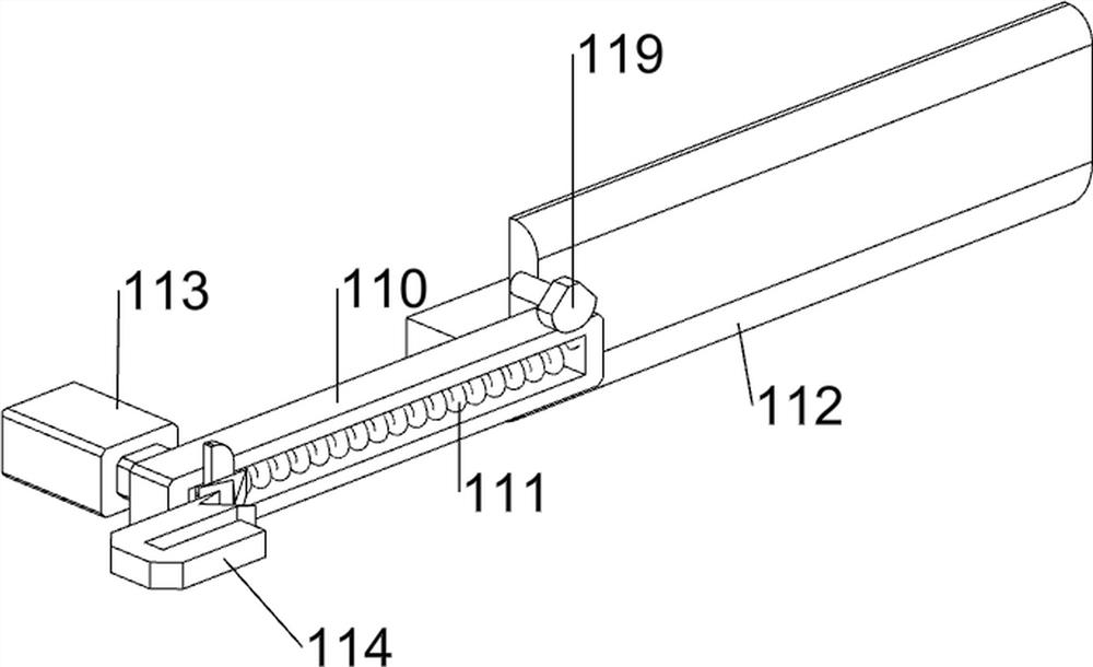
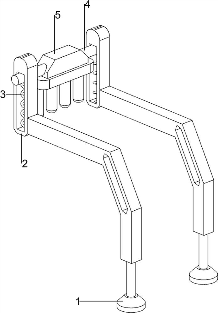
[0029] A metal high-grade inflatable lighter quality inspection machine, such as Figure 1-5 As shown, it includes a support foot 1, a first slide rail 2, a first spring 3, a connecting rod 4, a lower pressing rod 5, a placing mechanism 6 and a propulsion mechanism 7, and the support foot 1 is provided with a first slide rail 2, and the first A connecting rod 4 is slidably connected to the slide rail 2, and a first spring 3 is provided between the bottom of the connecting rod 4 and the first slide rail 2 on the same side, and a lower pressure rod 5 is connected between the connecting rod 4, and a supporting leg 1 The rear side is placed with a placement mechanism 6, and the placement mechanism 6 is provided with a propulsion mechanism 7.

[0030] The placement mechanism 6 includes a first support base 60, a first mounting plate 61, a second support base 62, a second mounting plate 63 and a baffle plate 64. Two first support bases 60 are placed on the rear side of the leg 1. Th...

Embodiment 2

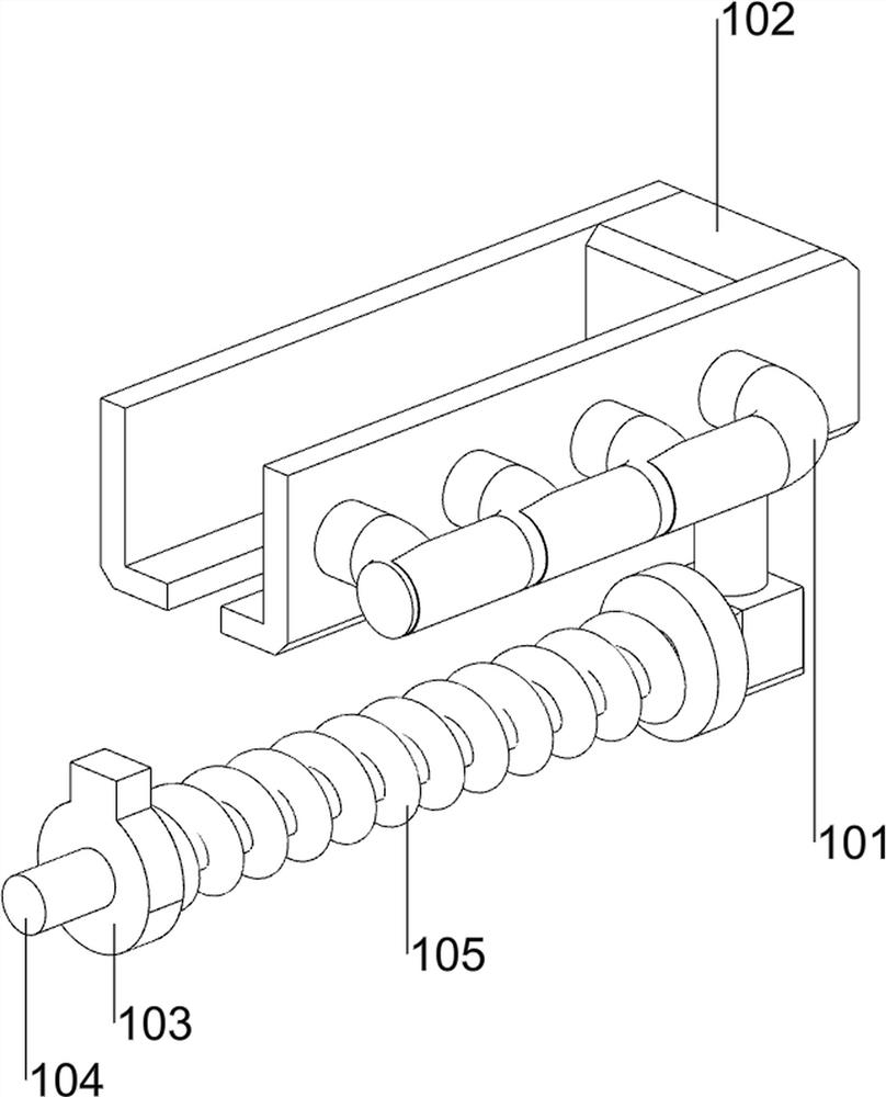
[0034] On the basis of Example 1, such as Figure 6-11 Shown, also comprise elevating mechanism 8, elevating mechanism 8 comprises advancing plate 80, connecting plate 81, advancing plate 82, connecting block 83, connecting column 84 and descending plate 85, hollow pipe 72 is provided with advancing plate 80, advances Plate 80 top, left and right sides are all provided with connecting plate 81, and connecting plate 81 tops are all provided with advance plate 82, and lower pressure bar 5 rear side is provided with connecting block 83, and connecting block 83 is provided with connecting column 84, and connecting column 84 left and right Both sides are provided with drop plate 85.

[0035] The hollow tube 72 moves forward to drive the forward plate 80, the connecting plate 81 and the forward plate 82 to move forward. When the forward plate 82 and the descending plate 85 are in contact, it drives the connecting block 83 and the connecting column 84 to move downward, thereby making...


PUM


Abstract

The invention relates to a detection machine, in particular to a quality detection machine for a high-grade metal inflatable lighter. The technical problem is to provide the quality detection machine for the metal high-grade inflatable lighter, which can realize automatic detection and automatic discharging. According to the technical scheme, the quality detection machine for the metal high-grade inflatable lighter comprises supporting legs, first sliding rails, first springs, connecting rods, a pressing rod, a placing mechanism and a pushing mechanism. The supporting legs are provided with the first sliding rails, and the first sliding rails are connected with the connecting rods in a sliding mode. First springs are arranged between the bottoms of the connecting rods and the first sliding rails on the same side, a lower pressing rod is connected between the connecting rods, a placing mechanism is placed on one side of the supporting legs, and a pushing mechanism is arranged on the placing mechanism. Through the cooperation of the placing mechanism, the propelling mechanism and the lifting mechanism, the lighter can be automatically pushed, and the lighter is automatically pressed for ignition.

Description

technical field [0001] The invention relates to a testing machine, in particular to a quality testing machine for metal high-grade inflatable lighters. Background technique [0002] Lighters are mainly used for smoking and making fire, and are also used for cooking and other fires. The main components of the lighter are the ignition mechanism and the gas storage tank. At this time, it is necessary to carry out quality inspection on the lighter, ignite the lighter on the same side, and then judge whether the lighter is useful according to whether there is a spark when igniting. [0003] Now it is usually manually detected, which is not only inefficient, but also easy to hurt people. Therefore, a quality inspection machine for metal high-grade inflatable lighters that can realize automatic detection and automatic discharge is now developed. Contents of the invention [0004] In order to overcome the shortcomings of manual detection, which is not only low in efficiency, but ...

Claims


Application Information

Patent Timeline
Patent Type & Authority Applications(China)
IPC IPC(8): G01M99/00F23Q23/00
CPCG01M99/005G01M99/008F23Q23/00
Inventor 毛福存
Owner 毛福存
Learn More