Building glass fiber reinforced plastic oiling and cloth winding device
A glass fiber reinforced plastic, wrapping technology, applied in the direction of the spray device, etc., can solve the problems of slow painting and wrapping speed, etc.
- Summary
- Abstract
- Description
- Claims
- Application Information
AI Technical Summary
Problems solved by technology
Method used
Image
Examples
Embodiment 1
[0025] A construction fiberglass oiling cloth wrapping device, such as Figure 1-8 Shown, include base 1, wrapping mechanism 2 and painting mechanism 3, base 1 upper left side is provided with wrapping mechanism 2, base 1 upper left side is provided with painting mechanism 3, wrapping mechanism 2 cooperates with painting mechanism 3.
[0026] When the user needs to oil and wrap the FRP, he can use this equipment. First, the FRP is placed on the wrapping mechanism 2 and the painting mechanism 3. Since the wrapping mechanism 2 and the painting mechanism 3 are placed crosswise, the user can manually Push the FRP to move to the left, pass through the wrapping mechanism 2 and the painting mechanism 3 in turn, and under the cooperation of the wrapping mechanism 2 and the painting mechanism 3, oil and wrap the FRP.
Embodiment 2
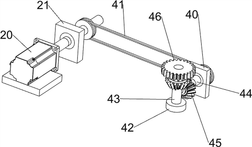
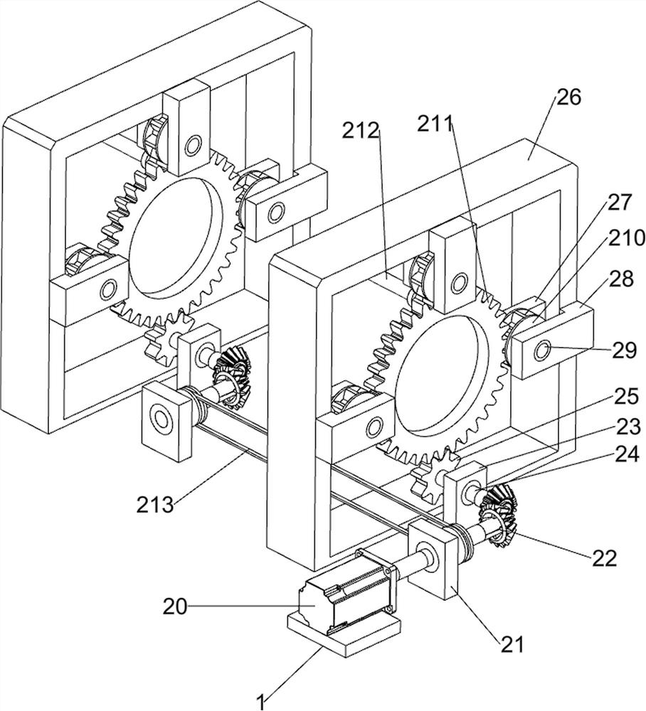
[0028] On the basis of Example 1, such as figure 2As shown, the cloth wrapping mechanism 2 includes a servo motor 20, a first bearing seat 21, a first bevel gear set 22, a second bearing seat 23, a first rotating shaft 24, a first gear 25, a mounting frame 26, and a third bearing seat 27. The fourth bearing seat 28, the second rotating shaft 29, the second gear 210, the third gear 211, the discharge rod 212 and the first pulley assembly 213, a servo motor 20 is arranged in the middle of the upper front side of the base 1, and the upper front of the base 1 The left and right sides of the side are symmetrically provided with the first bearing seat 21, the output shaft of the servo motor 20 passes through the first bearing seat 21 on the right side, the left and right sides of the base 1 top are symmetrically provided with the second bearing seat 23, the first bearing seat 23 on the left side The bearing seat 21 and the second bearing seat 23 on both sides are all rotatably prov...
Embodiment 3
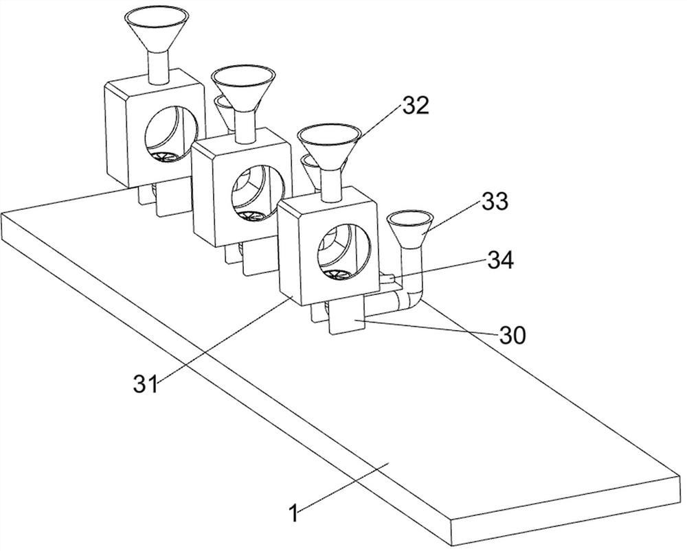
[0031] On the basis of Example 2, such as Figure 3-4 As shown, the painting mechanism 3 includes a support plate 30, a protective frame 31, an upper nozzle 32, a lower nozzle 33 and a discharge pipe 34, and the left side of the upper part of the base 1 is evenly provided with three support plates 30, and the upper part of the support plate 30 is equipped with Protective frame 31 is arranged, and protective frame 31 tops are all provided with upper spray pipe 32, and protective frame 31 rear portions are all provided with lower spray pipe 33, and protective frame 31 rear portions are all connected with discharge pipe 34, and discharge pipe 34 and protective frame 31 connected.
[0032] The user can pass the FRP through the protective frame 31, and then spray paint evenly on the FRP through the upper nozzle 32 and the lower nozzle 33. The excess paint on the FRP will fall in the protective frame 31 and flow out through the discharge pipe 34, thereby using The operator can recy...
PUM
 Abstract
Description
Claims
Application Information
 - R&D
- Intellectual Property
- Life Sciences
- Materials
- Tech Scout
- Unparalleled Data Quality
- Higher Quality Content
- 60% Fewer Hallucinations
Browse by: Latest US Patents, China's latest patents, Technical Efficacy Thesaurus, Application Domain, Technology Topic, Popular Technical Reports.
© 2025 PatSnap. All rights reserved.Legal|Privacy policy|Modern Slavery Act Transparency Statement|Sitemap|About US| Contact US: help@patsnap.com


