
LED lamp driving circuit, control method and electronic equipment

A technology for driving circuits and LED lights, applied in electrical components and other directions, can solve problems such as poor dimming effect of LED light sources, achieve smooth dimming, reduce electromagnetic interference, and prevent lamp flickering.

Active Publication Date: 2021-07-23
SONG RES ELECTRONICS TECH
View PDF8 Cites 1 Cited by
  • Summary
  • Abstract
  • Description
  • Claims
  • Application Information

AI Technical Summary

Problems solved by technology

[0004] The main purpose of the present invention is to provide a LED lamp driving circuit, control method and electronic equipment, aiming to solve the poor dimming effect of LED light sources in the prior art question

Method used


Image

  • LED lamp driving circuit, control method and electronic equipment
  • LED lamp driving circuit, control method and electronic equipment
  • LED lamp driving circuit, control method and electronic equipment

Examples


no. 1 example

[0114] Based on the first embodiment of the present invention, propose the second embodiment of the present invention; Reference Figure 9 , Figure 9 It is a circuit diagram of the pulse modulation circuit of the second embodiment of the LED lamp driving circuit of the present invention; the pulse modulation circuit 400 includes a single-chip microcomputer unit 403 and a second auxiliary unit 404; wherein, the output terminal of the second auxiliary unit 404 is connected to the One end of the single-chip microcomputer unit 403 is connected, and the output end of the single-chip microcomputer unit 403 is coupled with one end of the analog dimming circuit 300;

[0115] The second auxiliary unit 404 is configured to receive the dimming control voltage signal, divide the dimming control voltage signal, and output the divided dimming control voltage signal to the single-chip microcomputer unit 403;

[0116] The second auxiliary unit 404 is further configured to receive the first ...


PUM


Abstract

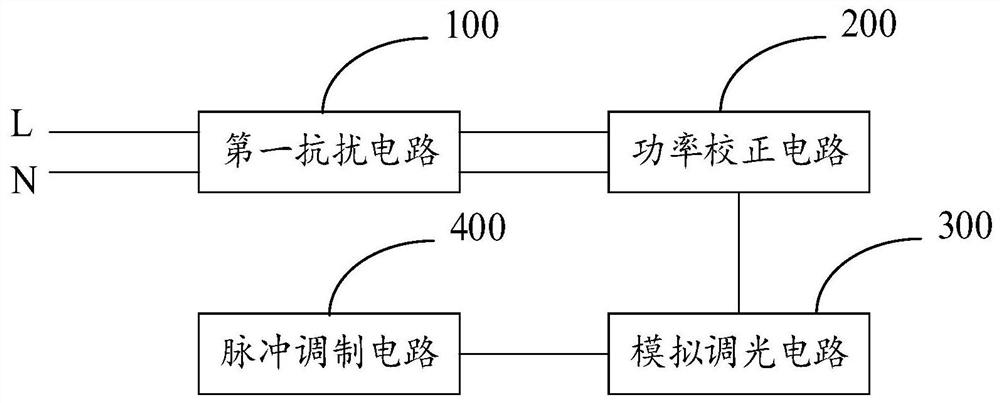
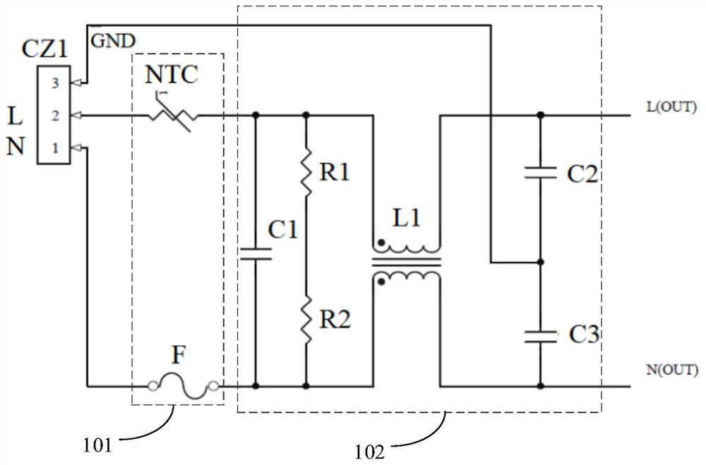
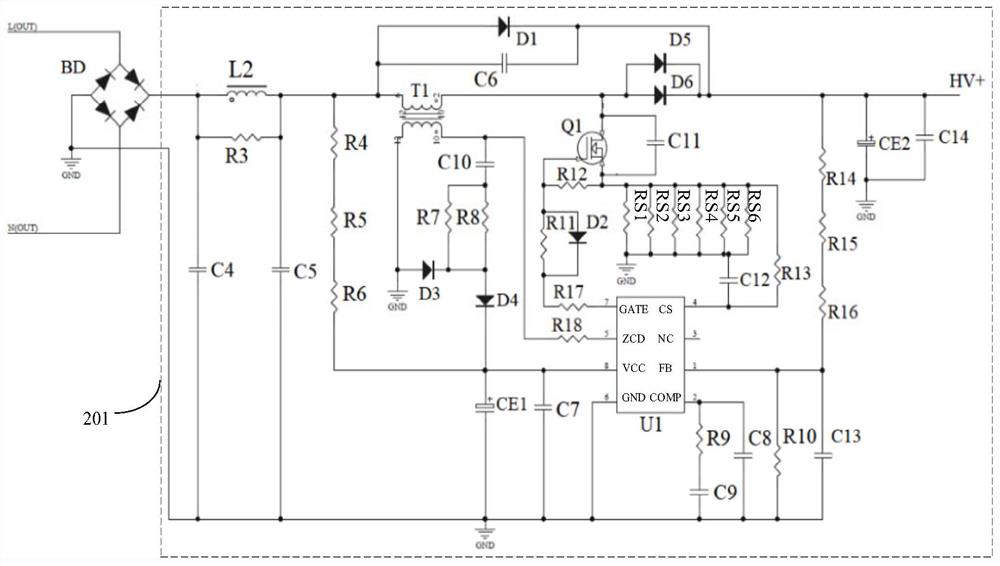
The invention belongs to the technical field of LED illumination, and discloses an LED lamp driving circuit, a control method and electronic equipment. The circuit comprises: a first anti-interference circuit which receives alternating current and filters the alternating current to obtain power supply voltage; a power correction circuit which performs power factor correction according to the power supply voltage to obtain a power correction voltage, and outputs the power correction voltage to the analog dimming circuit; a pulse modulation circuit which generates a pulse width modulation signal according to the dimming control voltage signal; and an analog dimming circuit which generates a constant-current power supply voltage corresponding to the dimming control voltage signal according to the power correction voltage and the pulse width modulation signal, and supplies power to the LED through the constant-current power supply voltage. Through the circuit, electromagnetic interference is reduced, power factor correction is carried out, a pulse width modulation signal is generated through dimming, a stable constant-current power supply is provided, dimming of an LED lamp is more stable, and the phenomena of lamp flashing and the like are prevented.

Description

technical field [0001] The invention relates to the technical field of LED lighting, in particular to an LED lamp driving circuit, a control method and electronic equipment. Background technique [0002] At present, there are more and more demands for adjustable LED lighting. It is applied to phase-cut dimming of traditional light sources (incandescent lamps, resistive loads), and the output voltage is controlled by the phase angle of the input voltage. The cost is low and the wiring is convenient. , is widely used. However, for LED light sources (capacitive loads), phase-cut dimming will cause compatibility problems such as flickering, insufficient dimming depth, and uneven dimming curve. [0003] The above content is only used to assist in understanding the technical solution of the present invention, and does not mean that the above content is admitted as prior art. Contents of the invention [0004] The main purpose of the present invention is to provide an LED lamp ...

Claims


Application Information

Patent Timeline
Patent Type & Authority Applications(China)
IPC IPC(8): H05B45/37H05B45/355H05B45/325H05B45/345
CPCH05B45/37H05B45/355H05B45/325H05B45/345
Inventor 杨锡凡
Owner SONG RES ELECTRONICS TECH
Learn More