Eureka AIR delivers breakthrough ideas for toughest innovation challenges, trusted by R&D personnel around the world.

Broken nail taking-out device for orthopedics department

A removal device and orthopedic technology, applied in the medical field, can solve problems such as lack of good fixation and limit measures at the treatment site, unfavorable patient recovery, secondary injuries, etc., and achieve the effects of convenient knife setting, reduced vibration, and avoiding injuries

Pending Publication Date: 2021-07-27
FOURTH MILITARY MEDICAL UNIVERSITY
View PDF0 Cites 0 Cited by
  • Summary
  • Abstract
  • Description
  • Claims
  • Application Information

AI Technical Summary

Problems solved by technology

[0002] Fracture is a common disease in orthopedic clinics. After a fracture occurs, the fracture site is usually reset first, and then the fracture site is fixed with screws and plates. After the fracture site is healed, the screw is screwed out of the patient's bone and Plate removal; the existing orthopedic broken nail removal device has a single structure and is usually manually operated by a doctor. There are no good fixation and limit measures for the patient's treatment site, and it is easy to cause secondary damage to the patient's treatment site during the nail removal process. Is not conducive to the recovery of patients; therefore, it is necessary to improve the existing technology

Method used


Image

  • Broken nail taking-out device for orthopedics department
  • Broken nail taking-out device for orthopedics department
  • Broken nail taking-out device for orthopedics department

Examples


Embodiment 1

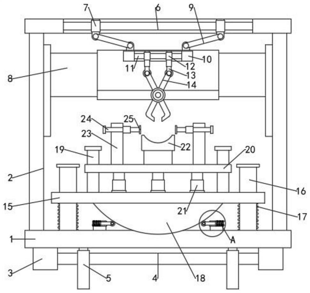
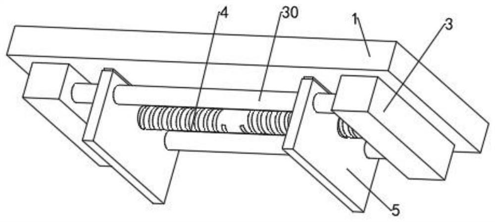
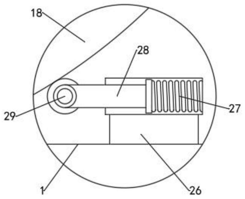
[0019] see Figure 1-3 , a device for removing broken orthopedic nails, comprising a base 1, a mounting frame 2 is fixed on the base 1, the cross section of the mounting frame 2 is a door frame shape, a tweezer 14 is movably installed on the inner side of the mounting frame 2, and a tweezer 14 is movably mounted on the base 1 There is a base plate 15, and a limit mechanism is arranged on the base plate 15; a cavity 8 is slidably installed on the inner side of the mounting frame 2, and a horizontal feed screw 6 is installed on the inner upper part of the mounting frame 2, and one end of the feed screw 6 extends To the inside of the mounting frame 2 and the transmission is connected with a motor, the inner side of the cavity 8 is rotated with a tweezer 14, and one end of the tweezer 14 extends to the outer lower part of the cavity 8, and the inner side of the cavity 8 is provided with a base 10. A horizontal adjusting screw 11 is installed in the seat 10, and one end of the adju...

Embodiment 2

[0028] In order to improve the clamping force of the tweezers 14 on the broken nails and avoid slipping during the removal of the broken nails, this embodiment is improved on the basis of Example 1. The improvements are: the tweezers 14 and the broken nails Uniform anti-slip lines are arranged on the contact surface to increase the clamping force on broken nails and facilitate the removal of broken nails.


PUM


Abstract

The invention relates to a broken nail taking-out device for orthopedics department, which comprises a base, a mounting frame is fixed to the base, the section of the mounting frame is in a door frame shape, tweezers are movably mounted on the inner side of the mounting frame, a base plate is movably mounted on the base, and a limiting mechanism is arranged on the base plate; according to the broken nail taking-out device for the orthopedics department, a supporting plate is arranged to be matched with a fixing plate, the treatment part of a patient can be effectively fixed conveniently, the distance between a bottom plate and the tweezers is convenient to adjust, and tool setting is convenient; a buffer structure is arranged between the base plate and the base, so that vibration of the base plate in the operation process is effectively reduced, and injury to a patient is avoided; a limiting plate is movably mounted below the base, so that the broken nail taking-out device can be conveniently mounted and fixed; in addition, through cooperation of the adjusting lead screw and the guide telescopic rod, opening and closing of the tweezers can be conveniently controlled, and broken nails can be conveniently taken out.

Description

technical field [0001] The invention relates to the field of medical technology, in particular to a device for removing broken orthopedic nails. Background technique [0002] Fracture is a common disease in orthopedic clinics. After a fracture occurs, the fracture site is usually reset first, and then the fracture site is fixed with screws and plates. After the fracture site is healed, the screw is screwed out of the patient's bone and Plate removal; the existing orthopedic broken nail removal device has a single structure and is usually manually operated by a doctor. There are no good fixation and limit measures for the patient's treatment site, and it is easy to cause secondary damage to the patient's treatment site during the nail removal process. It is not conducive to the rehabilitation of patients; therefore, it is necessary to improve the prior art. Contents of the invention [0003] The object of the present invention is to provide a device for removing broken ort...

Claims


Application Information

Patent Timeline
IPC IPC(8): A61B17/92
CPCA61B17/92
Inventor 鲜航丛锐张航赵睿臧成五张建磊陈永祥史林赵长应
Owner FOURTH MILITARY MEDICAL UNIVERSITY
Why Eureka
Eureka Blog
Learn More