An Optimal Blanking Method for Chip Testing Automated Production Line

An automated production line and chip testing technology, applied in automated testing systems, electronic circuit testing, electrical measurement, etc., can solve the problems of machine space occupation, increased machine size, and insufficient compactness of the machine, so as to improve timeliness and The effect of design cost reduction, high practical significance and application prospect

Active Publication Date: 2022-06-21
珠海达明科技有限公司
View PDF0 Cites 0 Cited by
  • Summary
  • Abstract
  • Description
  • Claims
  • Application Information

AI Technical Summary

Problems solved by technology

When the first nozzle picks up the chip whose coordinates are (8, 0), nozzle 2 ~ nozzle 8 move at the same time a distance of 8× the distance between the tray columns. At this time, nozzle 2 ~ nozzle 8 move outside the tray, occupying A certain amount of machine space is required, resulting in a certain increase in the size of the entire machine, the machine is not compact enough, and the design cost is increased

Method used


Image

  • An Optimal Blanking Method for Chip Testing Automated Production Line
  • An Optimal Blanking Method for Chip Testing Automated Production Line
  • An Optimal Blanking Method for Chip Testing Automated Production Line

Examples


Embodiment Construction

[0018] Examples of the present invention are as follows.

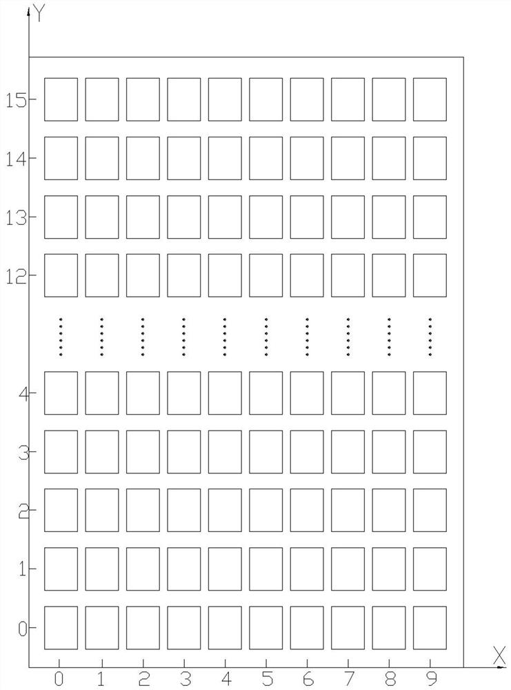
[0019] like figure 1 As shown, in the method of the present invention, the blanking equipment of the automatic chip testing production line is set as a tray, and the tray is provided with vertical and horizontally distributed chip positioning grooves, and a coordinate system is established with the vertically and horizontally distributed trays of the chip positioning grooves, and the horizontal direction of the tray is set as The X-axis is set as the Y-axis in the longitudinal direction of the tray, and the chip positioning grooves set on the tray are set to have m rows×n columns, where m and n are both natural numbers greater than 1, and m>n, and each chip positioning groove is set Set as a coordinate point, set the chip positioning slot of the first row and the first column as the origin of the coordinate system, the coordinate value is (X, Y)=(0,0), and the coordinates of the chip positioning slot of the first row a...


PUM


Abstract

The invention provides an optimal blanking method of an automatic chip testing production line capable of saving space, reducing cost and effectively improving efficiency. The method of the present invention improves the timeliness by optimizing the suction and placement path of the chip, thereby improving production efficiency; reducing the X-axis lateral movement distance of the variable-pitch suction nozzle module, saving space, making the machine more compact, reducing costs, and providing it to customers. More competitive products and services. The invention can be applied to the field of equipment control.

Description

technical field [0001] The invention relates to the field of equipment control, in particular to an optimal blanking method for an automated production line for chip testing. Background technique [0002] With the continuous development and progress of modern manufacturing technology, China spends a lot of manpower and material resources into manufacturing, especially the electronics manufacturing industry, which only earns product processing fees. Data: The net profit of business operations is only between 1% and 3%, and a little carelessness will lead to a loss. How to improve timeliness and reduce costs, provide customers with more competitive products and services, and create more profits, so that both parties can establish a more stable supply and demand relationship and achieve a win-win situation, has always been the goal of major manufacturing companies. [0003] In the blanking process of the chip test automation production line, in order to save costs, a blanking ...

Claims


Application Information

Patent Timeline
Patent Type & Authority Patents(China)
IPC IPC(8): G06F8/61B65G47/91B65G43/08G01R31/28B65G65/32
CPCB65G47/918B65G43/08G01R31/2834G01R31/2893B65G65/32
Inventor 符式鹏徐海东刘怡君张文超
Owner 珠海达明科技有限公司
Why Eureka
Try Eureka