Eureka AIR delivers breakthrough ideas for toughest innovation challenges, trusted by R&D personnel around the world.

Directional positioning fastener for sighting telescope

A technology for directional positioning and sights, which is applied in the field of sights and can solve the problems of cumbersome position adjustment of sights

Pending Publication Date: 2021-07-30
江苏金之润机械科技有限公司
View PDF0 Cites 0 Cited by
  • Summary
  • Abstract
  • Description
  • Claims
  • Application Information

AI Technical Summary

Problems solved by technology

[0004] The purpose of the present invention is to provide a sight directional positioning fastener in order to solve the problem of cumbersome position adjustment of the sight

Method used


Image

  • Directional positioning fastener for sighting telescope
  • Directional positioning fastener for sighting telescope
  • Directional positioning fastener for sighting telescope

Examples


Embodiment Construction

[0021] The following will clearly and completely describe the technical solutions in the embodiments of the present invention with reference to the accompanying drawings in the embodiments of the present invention. Obviously, the described embodiments are only some, not all, embodiments of the present invention. Based on the embodiments of the present invention, all other embodiments obtained by persons of ordinary skill in the art without making creative efforts belong to the protection scope of the present invention.

[0022] In the description of the present invention, it should be noted that the terms "center", "upper", "lower", "left", "right", "vertical", "horizontal", "inner", "outer" etc. The indicated orientation or positional relationship is based on the orientation or positional relationship shown in the drawings, and is only for the convenience of describing the present invention and simplifying the description, rather than indicating or implying that the referred d...


PUM


Abstract

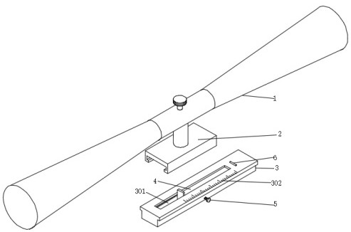
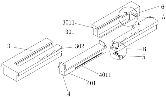
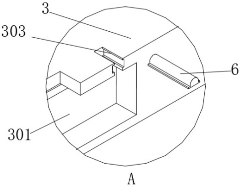
The invention discloses a directional positioning fastener for a sighting telescope, and relates to the technical field of sighting telescopes. The directional positioning fastener comprises the sighting telescope, a T-shaped rail, a fixing mechanism and a positioning mechanism, the bottom end of the sighting telescope is connected with a connecting seat, the T-shaped rail is mutually sleeved with the inner wall of the bottom end of the connecting seat, and a sliding groove and scale marks are formed in the top end of the T-shaped rail. The connecting seat and the T-shaped rail are connected in a sleeved mode so that the sighting telescope can be rapidly installed, the connecting seat can extrude a lifting block when being in contact with the lifting block, the lifting block can move downwards and push a telescopic block to slightly move downwards, and therefore the telescopic block can be conveniently separated from a lifting groove, the connecting seat can drive a sliding base to move through a fixing block, when the sliding base moves to drive a telescopic block to be separated from the inner wall of the T-shaped rail, the telescopic block can automatically reset and move upwards under the action of a telescopic spring, at the moment, the connecting seat is located between the telescopic block and the fixing block, and butt joint installation of the connecting seat and the T-shaped rail is completed.

Description

technical field [0001] The invention relates to the field of scope technology, in particular to a scope orientation and positioning fastener. Background technique [0002] The origin of sights or optical sighting devices is difficult to verify. It is said that at least as early as the 16th century in Europe, someone had tried to fix glasses on the butt of a gun. There are written records that before the 19th century, there were already telescopes on firearms. Type aiming device, which can be used for aiming in low light conditions. [0003] When the existing scope is installed on the gun barrel, a positioning fastener is generally used to make the installation of the scope more convenient, but the structure of the existing scope directional positioning fastener is generally more complicated. The adjustment operation is cumbersome, and it is not convenient to adjust the position of the sight, resulting in the sight not being replaceable to adapt to the use of different users...

Claims


Application Information

Patent Timeline
Patent Type & Authority Applications(China)
IPC IPC(8): F41G1/14F41G1/26
CPCF41G1/14F41G1/26
Inventor 殷俊殷煜
Owner 江苏金之润机械科技有限公司
Why Eureka
Eureka Blog
Learn More