Part detection mechanism based on machine vision and use method thereof

A technology of machine vision and detection mechanism, which is applied in the field of parts detection and can solve problems such as occlusion

Active Publication Date: 2021-07-30
ZHENGZHOU UNIVERSITY OF LIGHT INDUSTRY
View PDF22 Cites 4 Cited by
  • Summary
  • Abstract
  • Description
  • Claims
  • Application Information

AI Technical Summary

Problems solved by technology

[0011] The purpose of the present invention is to address the deficiencies in the prior art. This paper proposes a part detection mechanism based on

Method used


Image

  • Part detection mechanism based on machine vision and use method thereof
  • Part detection mechanism based on machine vision and use method thereof
  • Part detection mechanism based on machine vision and use method thereof

Examples


Embodiment Construction

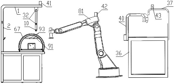
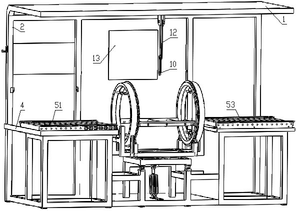
[0117] like Figure 1 to Figure 18 As shown, the part detection mechanism based on machine vision of the present invention includes a frame 2, with the overall moving direction of the detected part 31 as the downstream direction, and the frame 2 is sequentially provided with an input transmission mechanism 51, a clamping Shooting mechanism 52 and output transmission mechanism 53; The transmission surface of input transmission mechanism 51 is flush with the transmission surface of output transmission mechanism 53; The frame 2 is also provided with an electric control device 20, and the electric control device 20 is connected with a display screen 13 and an audio system. Optical alarm 19, with an image recognition module in the electric control device 20;

[0118] The clamping and shooting mechanism 52 includes a camera mechanical arm 12 hinged at the top of the frame 2 and a clamping device installed at the middle and lower part of the frame 2; the camera mechanical arm 12 is d...


PUM


Abstract

The invention discloses a part detection mechanism based on machine vision, which comprises a rack, an input conveying mechanism;with the overall moving direction of the detected part as the downstream direction, an input conveying mechanism, a clamping shooting mechanism and an output conveying mechanism are sequentially arranged on the rack from the upstream direction to the downstream direction; an electric control device is further arranged on the rack, the electric control device is connected with a display screen and an audible and visual alarm, and an image recognition module is arranged in the electric control device; the clamping shooting mechanism comprises a camera mechanical arm and a clamping device installed on the lower middle portion of the rack. A first camera is arranged at the free end of the camera mechanical arm, an illuminating lamp is arranged at the free end of the camera mechanical arm or on a fixing structure above the camera mechanical arm, and the servo motor, the illuminating lamp and the first camera are all connected with an electric control device; the clamping device comprises a clamping structure used for clamping a part, a longitudinal rotating structure used for driving the clamping part to rotate, a transverse rotating structure and a longitudinal overturning structure. The part detection mechanism further comprises a magnetic powder detection device.

Description

technical field [0001] The invention relates to the technical field of component detection, in particular to the component surface defect detection technology based on machine vision. Background technique [0002] Cracks on the surface of parts not only affect the overall quality of the part, but also cause damage to the interests of the manufacturer of the part, and may even cause serious accidental injury. For example, cracks appear in parts made of ferromagnetic materials such as shafts, gears, and disk sleeves in industries such as automobiles, military industry, aerospace, and track transmission, which may cause serious traffic accidents. Therefore, detecting and identifying the cracks on the surface of these magnetic parts has become a necessary means to measure the quality of the product. At present, the commonly used detection methods for surface cracks of ferromagnetic materials include turbine method, ultrasonic method, magnetic particle method and so on. [0003...

Claims


Application Information

Patent Timeline
IPC IPC(8): G01N21/01G01N21/892G01N27/84
CPCG01N21/01G01N21/892G01N27/84
Inventor 马军李晓科徐倩曹阳明五一何文斌龙雨都金光段留洋刘琨
Owner ZHENGZHOU UNIVERSITY OF LIGHT INDUSTRY
Why Eureka
Try Eureka