Device for attracting and killing farmland lepidoptera pest ostrinia nubilalis larvae by using attractant
A technology for Lepidoptera and corn borer, which is applied to the field of attracting and killing devices for lepidopteran pests corn borer larvae in farmland, can solve the problems of reducing the usability of the device, flying insects flying out, and being difficult to adapt to trapping and killing, etc. Insecticidal efficiency and performance improvement effect
- Summary
- Abstract
- Description
- Claims
- Application Information
AI Technical Summary
Problems solved by technology
Method used
Image
Examples
Embodiment 1
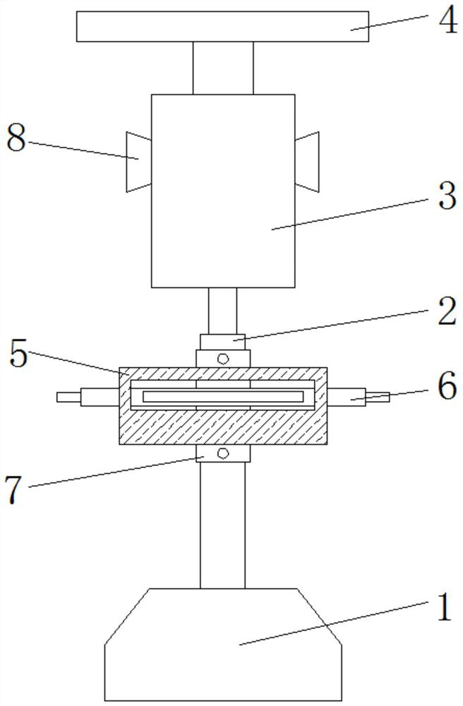
[0040] See Figure 1 to 8 According to the present invention, it provides a technical solution for a farmland lepidoptera-insect corn kervae induced killing device: a farmland larvae induced by a larvae induced killing device, including a base 1, and the upper end surface of the base 1. A telescopic rod 2 is mounted, and the upper end surface of the telescoping rod 2 is fixedly mounted, and the tube 7 is attached to the outer side of the sleeve 7, and the outer side of the sleeve 7 is fixedly mounted. 5;
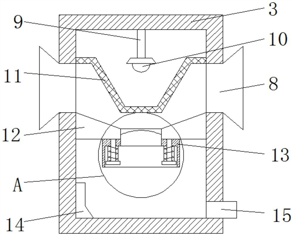
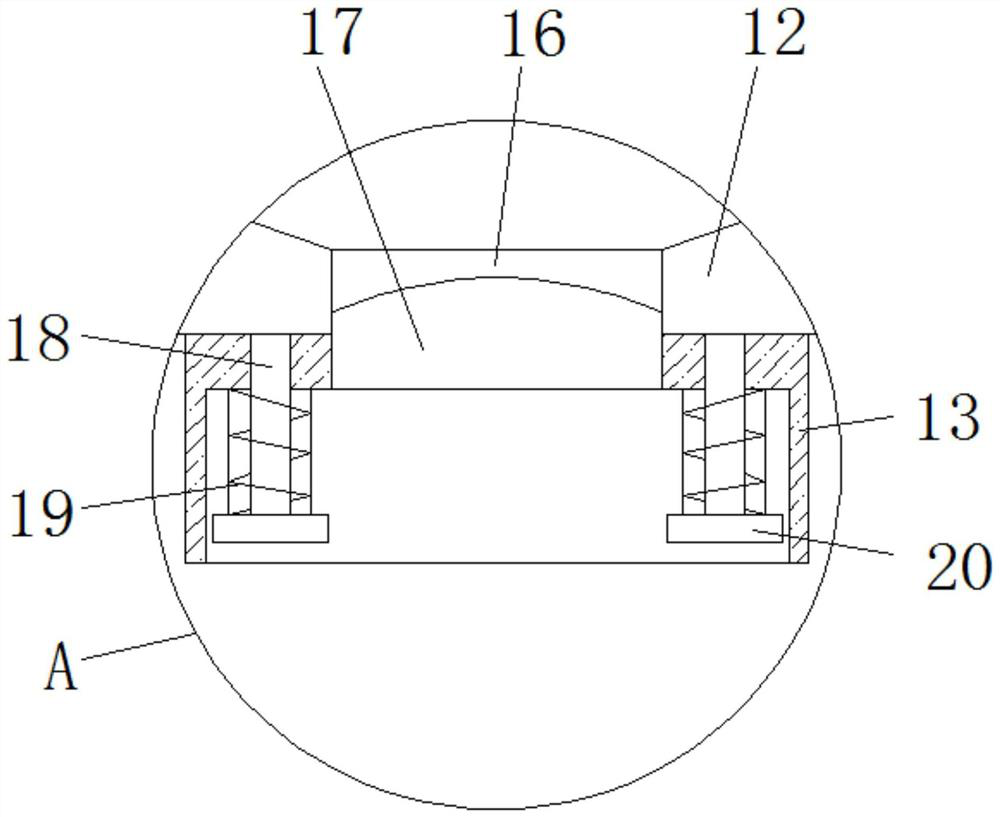
[0041] The sides of the laminated case 3 are fixedly mounted, and the position of the insectal strip 8 is attached. The position is fixed to the upper end of the inner tip of the cartridge 3, and the lower end surface of the lane 9 is fixedly mounted, and the induction of the insect lamp 10 is attached, the inside of the lane 3 is close to the upper end. The position is fixedly installed with a conical grid 11, the trace lamp 10 is located inside the grid 11, and the inner interm...
Embodiment 2
[0049] like Figure 5 and Image 6 As shown in the same manner as in Example 1, the difference from the first embodiment is:
[0050] The outer side surface of the telescoping rod 2 has several slide grooves 25, and several chute 25 are uniformly distributed, and the inner wall of the sleeve 7 is fixedly mounted, and the slider 26 matches the slide 25.
[0051] The inside of the sleeve 7 is rotated and mounted to the outer portion of the sleeve 27 extends to the outer portion of the sleeve 7, and the internal threaded joint finite bit rod 28 of the drum 27, and the limit slot is opened on both sides of the limit rod 28. 29, the internal fixation mounting of the sleeve 7, the limit panel 30 is corresponding to the limit slot 29, and the restricted rod 28 is open to the position of the telescopic rod 2 with a tooth groove 31, both The tooth groove 31 matches.
[0052] Working principle: Turn the drum 27, under the action of thread, the guiding action of the limit slot 29 and the limit...
Embodiment 3
[0054] like Figure 7 to 8 As shown in the same manner as in Example 1, the difference from the first embodiment is:
[0055] The inner portion of the guide plate 6 is opened, and the internal sliding of the movable groove 35 is slidably mounted, and the moving plate 38 is fixedly mounted on both sides of the extension plate 33, and the internal upper end of the movable groove 35 is left away from the position of the cartridge 3. 36. The upper end surface of the pressure plate 36 is fixed to the movable groove 35, and the second spring 37 is mounted, and the second spring 37 is inserted through the tie rod 34, and the tie rod 34 is fixedly mounted at the upper end of the pressure plate 36.
[0056] The top end of the tie rod 3 extends to the upper end of the guide plate 6 and is fixedly mounted, and the two movable grooves 35 respectively symmetrically, the pressure plate 36 corresponds to the moving plate 38.
[0057] The guide plate 6 is provided with a non-slip protrus, and the ...
PUM
 Abstract
Description
Claims
Application Information
 - R&D
- Intellectual Property
- Life Sciences
- Materials
- Tech Scout
- Unparalleled Data Quality
- Higher Quality Content
- 60% Fewer Hallucinations
Browse by: Latest US Patents, China's latest patents, Technical Efficacy Thesaurus, Application Domain, Technology Topic, Popular Technical Reports.
© 2025 PatSnap. All rights reserved.Legal|Privacy policy|Modern Slavery Act Transparency Statement|Sitemap|About US| Contact US: help@patsnap.com


