Automatic part feeding device for machining

A technology of automatic feeding and machining, which is applied to conveyor objects, packaging, transportation and packaging, etc., can solve the problems of difficult-to-shape irregular parts feeding, low efficiency, poor sorting and feeding accuracy, etc. High performance, high conveying efficiency, and the effect of ensuring stability

Inactive Publication Date: 2021-08-03
义乌市今朝创意设计有限公司
View PDF0 Cites 0 Cited by
  • Summary
  • Abstract
  • Description
  • Claims
  • Application Information

AI Technical Summary

Problems solved by technology

[0003] The object of the present invention is to provide an automatic feeding device for parts for machining, which solves the problem of poor applicability, poor sorting and feeding accuracy, low efficiency, and difficulty in correcting the shape of the automatic parts feeding device for machining in the prior art. Irregular parts are loaded, and parts are prone to problems such as overflow and damage

Method used


Image

  • Automatic part feeding device for machining
  • Automatic part feeding device for machining
  • Automatic part feeding device for machining

Examples


no. 1 example

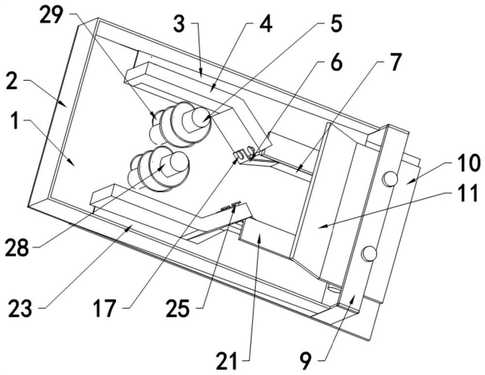
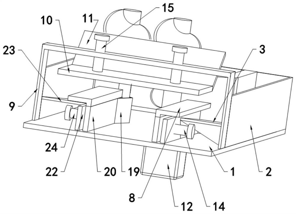
[0033] refer to Figure 1-6, an automatic feeding device for machining parts, comprising a base 1, the two sides of the base 1 are symmetrically provided with a first side plate 4 and a second side plate 18, and the top of the base 1 is respectively provided with a first vertical plate 13 And the second vertical plate 22, the opposite sides of the first vertical plate 13 and the second vertical plate 22 are respectively provided with the first movable plate 7 and the second movable plate 20 by the first electric telescopic link 14 and the second electric telescopic link 24, The spacing between the first movable plate 7 and the second movable plate 20 can be adjusted, the first movable plate 7 is installed with the corresponding first side plate 4 by the first elastic band 6, and the second movable plate 20 is connected with the second elastic band 19 The second side plate 18 is installed, and the base 1 is provided with a fixed frame 9 with a downward U-shaped structure. The t...

no. 2 example

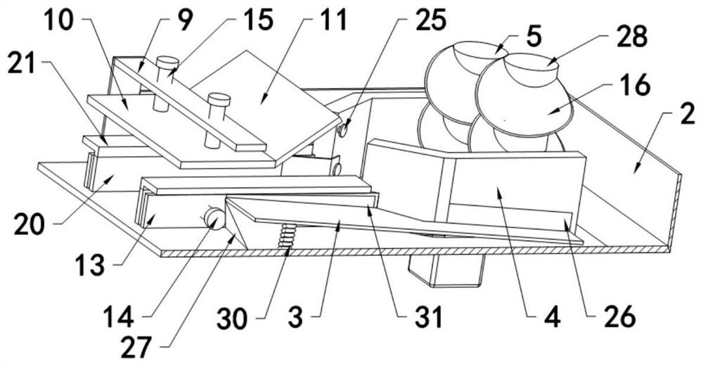
[0038] Based on the first embodiment, an automatic feeding device for machining parts is provided, which uses the rotation of the spiral undulating plate 16 to realize the parts entering the first movable plate 7, the second movable plate 20 and the limit plate 10 during specific use. , the so-called feeding process, but in actual use, only the screw shift piece 16 drives the part to rotate to realize that the end of the part just reaches the first movable plate 7, the second movable plate 20 and the port operation of the limit plate 10. Very large chance, so its feeding process efficiency is low, after the part enters the first movable plate 7, the second movable plate 20 and the limit plate 10, the screw driving piece 16 is still constantly rotating, so the first side plate 4 and the The parts in the second side plate 18 are still continuously rotating thereupon and carry out collision obstruction to the parts that have entered, thereby affecting the quality of parts and the ...


PUM


Abstract

The invention relates to an automatic part feeding device for machining. The device comprises a base, a first side plate and a second side plate are symmetrically arranged at the two sides of the base, discharging holes are formed in the first side plate and the second side plate, and a first vertical plate and a second vertical plate are symmetrically arranged at the top of the base; and inclined holes are formed in the first vertical plate and the second vertical plate correspondingly, and a first movable plate and a second movable plate are arranged at the opposite sides of the first vertical plate and the second vertical plate through a first electric telescopic rod and a second electric telescopic rod correspondingly. Through the arrangement of the first electric telescopic rod, the second electric telescopic rod and a top electric telescopic rod, the first movable plate, the second movable plate and a limiting plate can continuously move in the feeding process, and the moving size of the first movable plate, the second movable plate and the limiting plate is matched with the boundary dimension of parts; and in this way, in the feeding process of the parts, the positions of the parts can be accurately standardized and corrected, follow-up conveying is not affected, the parts do not interfere with one another in the feeding process, the conveying efficiency is high, and the conveying effect is good.

Description

technical field [0001] The invention relates to an automatic feeding device for machining parts. Background technique [0002] Feeder, also known as feeder, refers to a machine used to transport materials. Commonly used in the automatic, numerical control and precise conveying of materials such as pellets, powders, flakes and strips. It is an indispensable transmission equipment for both light industry and heavy industry. In the existing parts processing production line, the parts need to be transported to the processing position. During the feeding and conveying process of the parts, the state of the parts greatly affects the processing accuracy of the next production line; therefore, most of the existing parts are used to automatically transport parts by changing The shape of the feeding device defines the conveying state of the parts. However, most of the existing devices for feeding parts are fixed structures, which are not easy to adjust, and can only limit the autom...

Claims


Application Information

Patent Timeline
Patent Type & Authority Applications(China)
IPC IPC(8): B65G47/22B65G47/74B65G33/06B65G47/248B08B1/02
CPCB08B1/02B65G33/06B65G47/22B65G47/248B65G47/74
Inventor 朱堂葵
Owner 义乌市今朝创意设计有限公司
Why Eureka
Try Eureka