
A waterproof structure for water conservancy construction

A waterproof structure and water conservancy technology, applied in water conservancy projects, artificial waterways, roads, etc., can solve the problems of water infiltration, affecting the safe use of roads, unstable soil, etc., to increase the waterproof isolation area and improve the waterproofness. Efficiency, the effect of increasing safety performance

Active Publication Date: 2022-07-05
邓新超
View PDF5 Cites 0 Cited by
  • Summary
  • Abstract
  • Description
  • Claims
  • Application Information

AI Technical Summary

Problems solved by technology

[0005] In this patent application, a waterproof membrane is set between the canal and the road to achieve a good waterproof effect on the aqueduct, but the waterproof membrane is set between the canal and the road, and while waterproofing the two, it also causes The water at the subgrade of the road cannot penetrate well, and the impermeable water will cause the soil under the subgrade to be very unstable and affect the safe use of the road; at the same time, although waterproof materials, namely waterproof membranes are installed for waterproofing, the waterproof performance of the waterproof membrane not only depends on Due to the characteristics of waterproof materials, it is also affected by the state of the bottom layer and the external environment. For example, the water content of the bottom layer is high, and the vapor pressure of the waterproof membrane after construction and the production pressure between the low pressure will cause the soil at the waterproof material to be affected. The waterproof membrane is cracked or damaged due to the impact of the impact. For this reason, we propose a waterproof structure for water conservancy construction

Method used


Image

  • A waterproof structure for water conservancy construction
  • A waterproof structure for water conservancy construction
  • A waterproof structure for water conservancy construction

Examples


Embodiment Construction

[0032] The technical solutions in the embodiments of the present invention will be clearly and completely described below with reference to the accompanying drawings in the embodiments of the present invention. Obviously, the described embodiments are only a part of the embodiments of the present invention, but not all of the embodiments. Based on the embodiments of the present invention, all other embodiments obtained by those of ordinary skill in the art without creative efforts shall fall within the protection scope of the present invention.

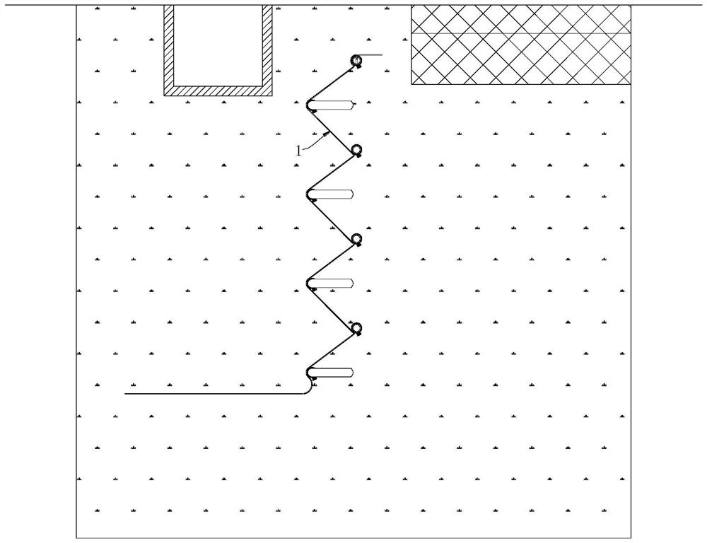
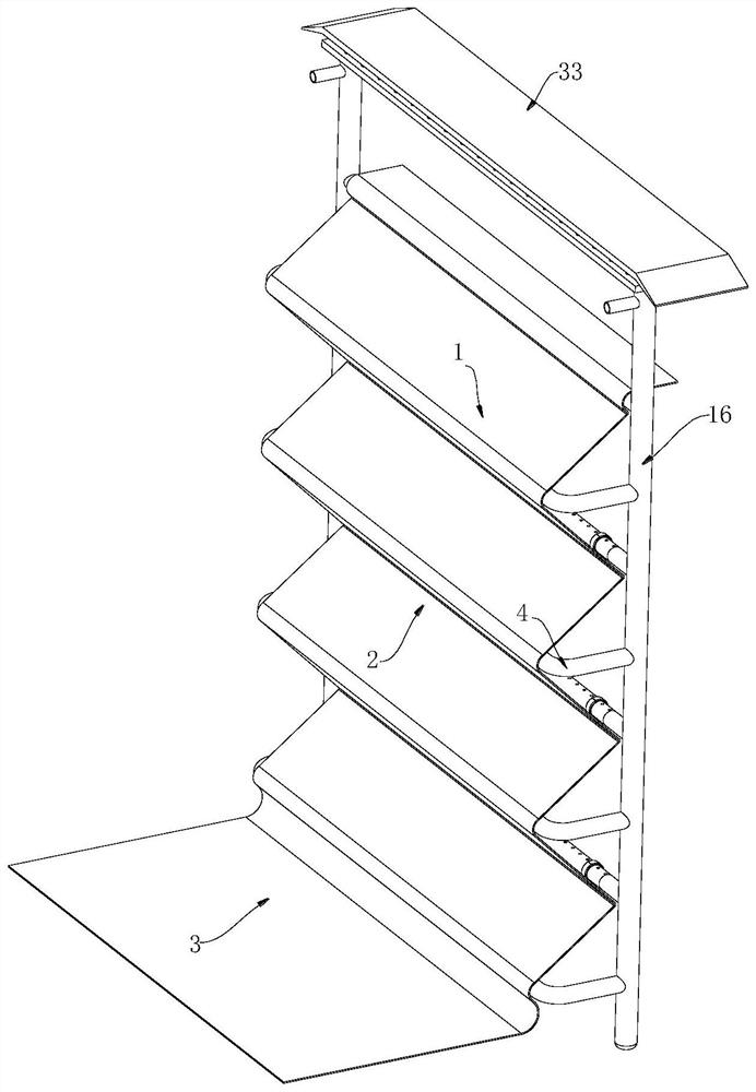
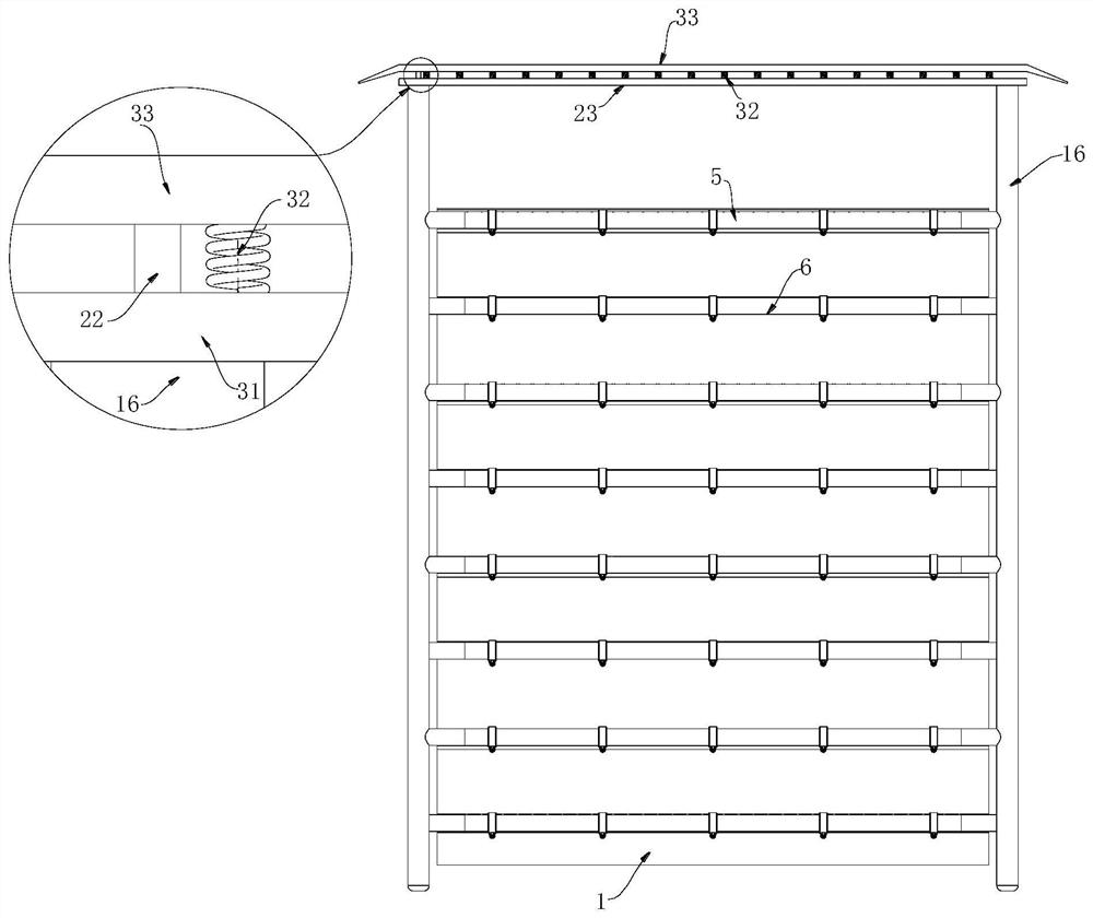
[0033] see Figure 1-9 , the present invention provides a technical solution: a waterproof structure for water conservancy construction, comprising a waterproof membrane 1 arranged at an underground trench, and the waterproof membrane 1 is installed in the outer trench to obtain a trench, and then the trench is filled, so that the The waterproof membrane 1 is located between the road and the diversion channel, and is used to isolate a...


PUM


Abstract

The invention discloses a waterproof structure for water conservancy construction, comprising a waterproof membrane arranged at an underground trench, the waterproof membrane is located between a road and a water diversion channel, and is used for water overflowing in the underground soil between the road and the diversion channel. Isolation and waterproofing, the waterproof membrane is composed of an upper section membrane and a lower section membrane, and a plurality of bends of the upper section membrane are provided with ventilation and drainage parts, and the ventilation drainage parts are used to place the waterproof membrane in the soil on the side of the road. The overflowing water is drained and discharged. This water conservancy construction waterproof structure not only increases the waterproof isolation area of ​​the waterproof membrane, but also has an effective waterproof effect on roads and diversion channels. Drainage parts, so that the water and gas overflowing from the soil on the side of the road are drained and discharged by the waterproof membrane, which effectively avoids the problem that the soil at the base end of the road contains a lot of water and causes the soil to become unstable, thus increasing the number of roads. safety performance.

Description

technical field [0001] The invention relates to the technical field of water conservancy construction, in particular to a waterproof structure for water conservancy construction. Background technique [0002] A water conservancy project is a project built for the purpose of controlling and deploying natural surface water and groundwater to achieve the purpose of eliminating harm and increasing profits. Also known as water engineering. Water is an indispensable and precious resource for human production and life, but its natural state does not fully meet human needs. Only by building water conservancy projects can we control water flow, prevent flood disasters, and adjust and distribute water to meet the needs of people's lives and production for water resources. Water conservancy projects require the construction of different types of hydraulic structures such as dams, embankments, spillways, sluice gates, water inlets, channels, ferries, rafts, fishways, etc., to achieve ...

Claims


Application Information

Patent Timeline
Patent Type & Authority Patents(China)
IPC IPC(8): E01C11/22E02B5/02E02B13/00
CPCE01C11/227E02B13/00E02B5/02Y02A30/60
Inventor 邓新超陈诗阳詹育玄
Owner 邓新超
Learn More