
Suction fan

A suction fan and wind pressure technology, which is applied to mechanical equipment, machines/engines, liquid fuel engines, etc., can solve problems such as inconvenient operation and reduced work efficiency, and achieve the effect of shortening response time and improving work efficiency

Pending Publication Date: 2021-08-03
SHENZHEN RUNTIANZHI DIGITAL EQUIP
View PDF0 Cites 0 Cited by
  • Summary
  • Abstract
  • Description
  • Claims
  • Application Information

AI Technical Summary

Problems solved by technology

However, the transmission of the motor and the fan blades has a hysteresis. When the suction fan needs to stop working, often only the motor can respond quickly after the power is turned off, and the fan blades will continue to rotate for a period of time due to inertia, which will cause the suction duct to stop working during this time. Suction is still generated inside, which causes inconvenience to the operation of intermittent operation machines with frequent switching and greatly reduces work efficiency

Method used


Image

  • Suction fan
  • Suction fan
  • Suction fan

Examples


Embodiment Construction

[0022] The present application will be described in further detail below in conjunction with the accompanying drawings and specific embodiments. It should be understood that the following exemplary embodiments and descriptions are only used to explain the present invention, not as a limitation to the present invention, and, in the case of no conflict, the embodiments in the application and the features in the embodiments can be combined with each other .

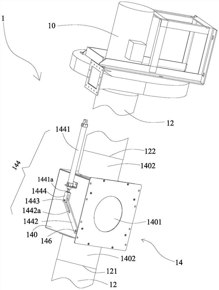
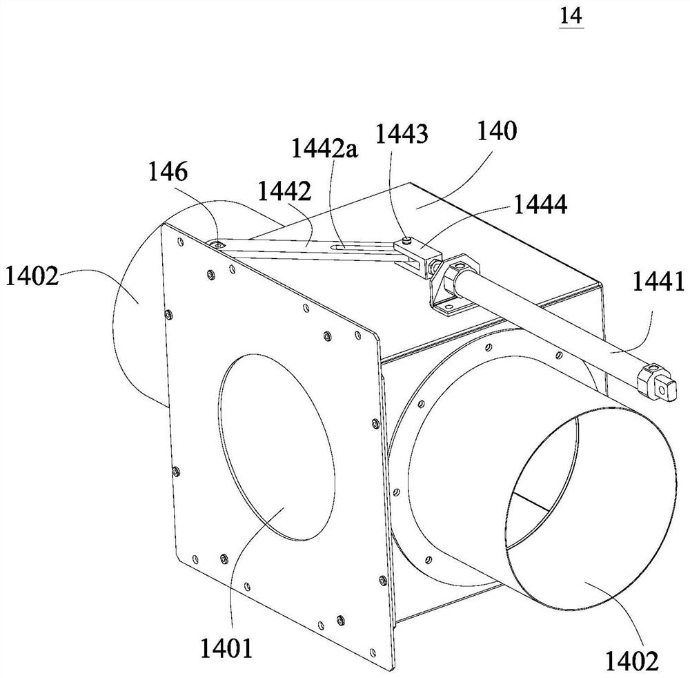
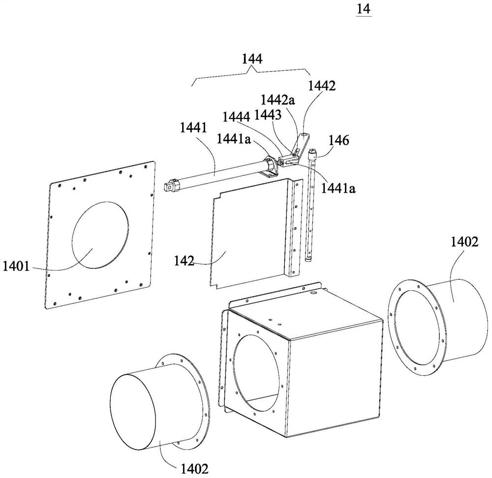
[0023] Such as Figure 1-Figure 7 As shown, an optional embodiment of the present invention provides a suction fan 1, including a suction assembly 10 and a suction duct 12 connected to the suction assembly 10, and the suction fan 1 also includes a suction pipe connected to the suction assembly 10. The air discharge assembly 14 in the pipeline 12, the air discharge assembly 14 includes two ends respectively connected to the upstream end 121 and the downstream end 122 of the suction pipe 12 and a wind pressure outlet 1401 is ...


PUM


Abstract

The embodiment of the invention provides a suction fan which comprises an air suction assembly, an air suction pipeline connected with the air suction assembly and an air discharging assembly connected into the air suction pipeline. The air discharging assembly comprises an air pressure releasing box, an air discharging opening cover plate and a drive piece, wherein the two ends of the air pressure releasing box are connected with the upstream end and the downstream end of air suction pipeline correspondingly, the air pressure releasing box is provided with an air discharging opening, and the drive piece is used for driving the cover plate to move between the covering position where the air discharging opening is closed and the opening position where the air discharging opening is opened. According to the suction fan, the air discharging assembly is arranged in the air suction pipeline of the suction fan, the air pressure release box provided with the air discharging opening is communicated with the air suction pipeline, and the driving piece drives the cover plate to move back and forth to cooperate with the air discharging opening to form air pressure or release air pressure. When the suction fan operates normally, the drive piece drives the cover plate to the covering position to cover the air discharging opening, and suction force is normally generated in the air suction pipeline. When the suction fan is switched off, the driving piece drives the cover plate to the open position, the air discharging opening is exposed, air pressure is released, suction force in the air suction pipeline can disappear rapidly, the response time of shutdown of the suction fan is shortened, and the operation efficiency is improved.

Description

technical field [0001] The embodiments of the present invention relate to the technical field of mechanical equipment, in particular to a suction fan. Background technique [0002] The suction fan is driven by the motor to rotate the fan blades to generate air flow to form wind pressure and generate suction. Therefore, the generation or disappearance of the suction fan suction is closely related to the rotation state of the fan blades. However, the transmission of the motor and the fan blades has a hysteresis. When the suction fan needs to stop working, often only the motor can respond quickly after the power is turned off, and the fan blades will continue to rotate for a period of time due to inertia, which will cause the suction duct to stop working during this time. Suction is still generated inside, which causes inconvenience to the operation of intermittent operation machines with frequent switching and greatly reduces work efficiency. Contents of the invention [00...

Claims


Application Information

Patent Timeline
Patent Type & Authority Applications(China)
IPC IPC(8): F04D25/08F04D29/40F04D29/60
CPCF04D25/08F04D29/403F04D29/601
Inventor 李文峰徐星郑俊雄江洪
Owner SHENZHEN RUNTIANZHI DIGITAL EQUIP
Learn More