Quick and accurate positioning device and method for mounting a channel on trolley
A technology for precise positioning and installation of grooves, which is applied in the direction of thin plate connections, threaded fasteners, connecting components, etc., can solve problems such as inability to accurately locate and quickly install, slide or slip in pre-buried grooves, and deviations, so as to save manpower and ensure Fastening effect, fast and precise positioning effect
- Summary
- Abstract
- Description
- Claims
- Application Information
AI Technical Summary
Problems solved by technology
Method used
Image

Examples
Embodiment 1
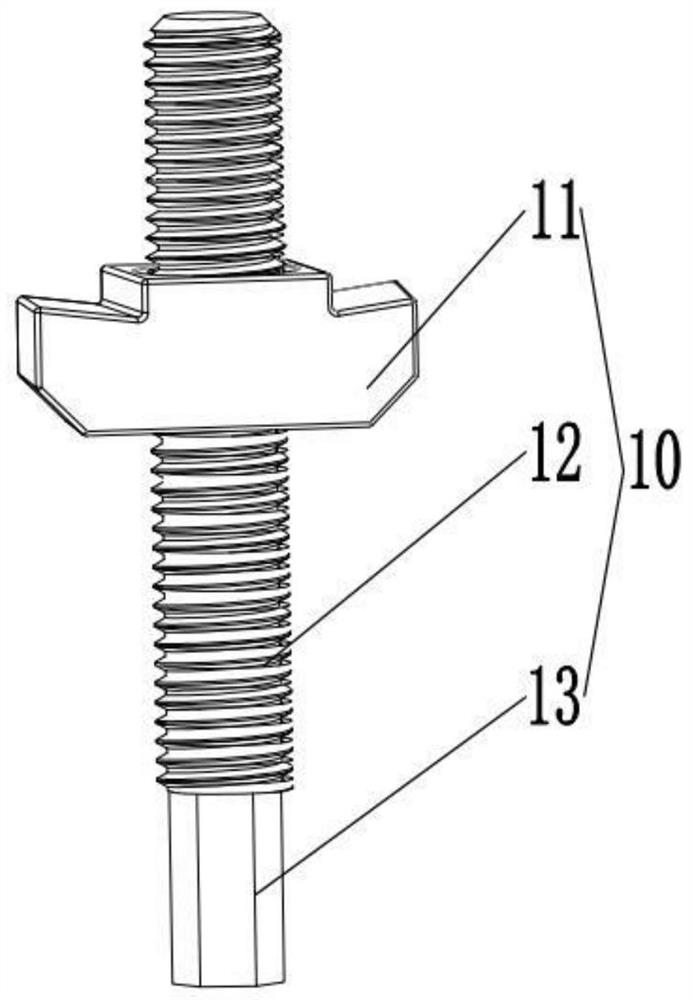
[0032] see figure 1 , as shown in the legend therein, a fast and precise positioning device for installing channels on trolleys, including self-positioning special-shaped fasteners 10, self-positioning special-shaped fasteners 10 including special-shaped fastener heads 11 and screw rods 12, special-shaped fasteners The piece head 11 and the screw rod 12 are separate structures, the special-shaped fastener head 11 is provided with a screw hole, and the screw rod 12 is threadedly connected in the screw hole.
[0033] In a preferred implementation of this embodiment, the shape of the special-shaped fastener head 11 of the self-positioning special-shaped fastener 10 is the same as the shape of the special-shaped fastener head of the T-shaped bolt.
[0034] In a preferred implementation manner in this embodiment, the special-shaped fastener head 11 is a parallelogram.
[0035] In a preferred implementation of this embodiment, one end surface of the screw 12 is a resisting end surf...
PUM
 Abstract
Description
Claims
Application Information
PatSnap Eureka turns technology decisions into work you can execute. Powered by our Innovation Knowledge Graph, it runs expert workflows across engineering, life sciences, materials and intellectual property. Get your review-ready output in minutes.


