Automatic assembling machine for IC packaging pipe rubber plug

A technology for automatic assembly and packaging of tubes, applied in assembly machines, metal processing, metal processing equipment, etc., can solve the problems of overall inconvenience, high labor costs, low work efficiency, etc., to save labor costs, low defective product rate, The effect of high work efficiency

Active Publication Date: 2018-10-19
泰州炬昕微电子有限公司
View PDF8 Cites 9 Cited by
  • Summary
  • Abstract
  • Description
  • Claims
  • Application Information

AI Technical Summary

Problems solved by technology

[0004] Since the assembly process of the rubber plug and the transparent packaging tube is very simple, there are two ways to assemble the rubber plug and the transparent packaging tube. One is to assemble directly by manual operation. The advantage of manual assembly is that it does not need to purchase any equipment Simple assembly is possible, while manual assembly has the disadvantages of low work efficiency and high labor costs; the other is assembly by semi-automatic assembly equipment, the existing semi-automatic assembly equipment has a simple structure, including rubber plugs for placing rubber plugs The jig and the tube jig used to place the transparent packaging tube are then assembled by manual operation. Each simple assembly equipment requires an operator to operate. The advantage of this semi-automatic assembly equipment is that the assembly efficiency is relatively high. The disadvantage is that the operator is still required to carry out loading, unloading, assembly and unloading, the overall operation is inconvenient, and some human resources need to be invested

Method used


Image

  • Automatic assembling machine for IC packaging pipe rubber plug
  • Automatic assembling machine for IC packaging pipe rubber plug
  • Automatic assembling machine for IC packaging pipe rubber plug

Examples


Embodiment Construction

[0025] The present invention will be further described in detail below in conjunction with the accompanying drawings and specific embodiments.

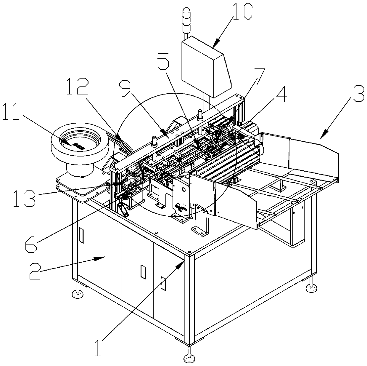
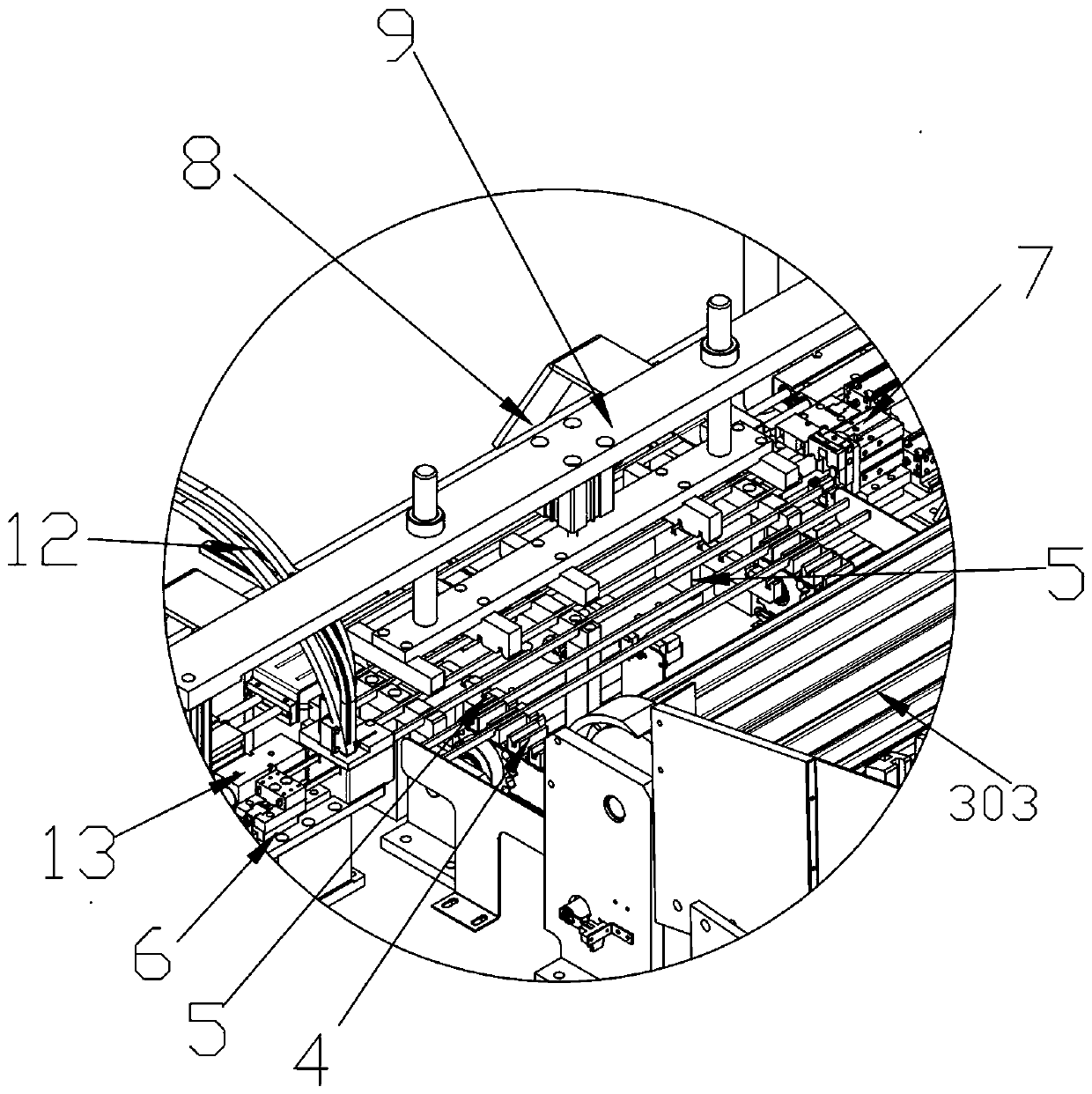
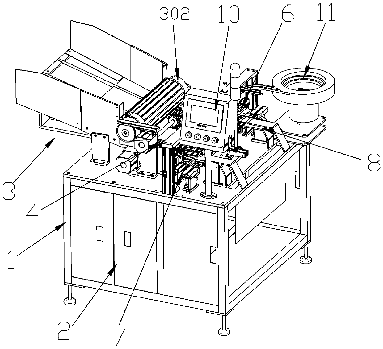
[0026] In this embodiment, refer to Figure 1-Figure 8, the IC packaging tube rubber stopper automatic assembly machine of its concrete implementation comprises frame 1 and automatic assembly platform, and the top of frame 1 is provided with plane mounting plate, and automatic assembly platform is installed on the plane mounting plate, and the interior of frame 1 is provided with The main control power distribution cabinet 2, the top of the frame 1 is provided with a man-machine exchange platform 10 electrically connected to the main control power distribution cabinet 2, the automatic assembly platform includes a rubber plug blanking mechanism 6, and a packaging tube rear end positioning mechanism 7 , the pre-pressing mechanism 9 and the material receiving mechanism, the rubber plug blanking mechanism 6 is arranged on the left end of ...


PUM


Abstract

The invention relates to an automatic assembling machine for an IC packaging pipe rubber plug in the field of automation equipment. The automatic assembling machine comprises a rack and an automatic assembling platform. A plane installing plate is arranged on the top of the rack. The automatic assembling platform comprises a rubber plug blanking mechanism, a packaging pipe rear end locating mechanism, a prepressing mechanism and a material receiving mechanism. A material transferring mechanism is further arranged between the rubber plug blanking mechanism and the packaging pipe rear end locating mechanism. An automatic feeding system is arranged at the front end of the automatic assembling platform. An automatic discharging mechanism is arranged at the rear end of the automatic assemblingplatform. The automatic feeding system comprises a packaging pipe blanking mechanism, a packaging pipe conveying mechanism and a material moving mechanism which are sequentially arranged from front toback. Compared with traditional manual assembling, the whole process is completed through automatic assembly line operation, automatic feeding, automatic assembling and automatic discharging can be achieved, the working efficiency is high, the defect rate is extremely low, a great deal of labor cost can be saved, and precise assembling and precise detecting can be achieved by means of the automation machine.

Description

technical field [0001] The invention relates to the field of automation equipment, in particular to the field of automatic assembly equipment. Background technique [0002] IC packaging tubes are IC, integrated circuits, integrated blocks, semiconductors, electronic components, transformer parts and precision electronic components and packaging tubes. They are mainly used as packaging materials to prevent damage to parts during transportation and to prevent damage during transportation. A packaging tube that prevents electrostatic damage to components caused by static electricity. [0003] The IC packaging tube is composed of a transparent packaging tube body and a rubber plug. One end of the transparent packaging tube body is a sealed end, and the rubber plug is paired into the other end of the transparent packaging tube body. Put the components into the transparent packaging tube, and then put on the rubber plug to play a good protective effect. On the contrary, directly ...

Claims


Application Information

Patent Timeline
Patent Type & Authority Applications(China)
IPC IPC(8): B23P21/00B23P19/00
Inventor 宋思宁
Owner 泰州炬昕微电子有限公司
Why Eureka
Try Eureka