Adjustable stent with buckle structure

An adjustable, body-based technology, which is applied to human body tubular structure devices, stents, medical science, etc., can solve the problems of easy formation of thrombus, vessel wall damage, thrombus formation, etc., to avoid stuck or locked, save materials, The effect of easy operation

Inactive Publication Date: 2021-08-06
赵晓辉
View PDF0 Cites 0 Cited by
  • Summary
  • Abstract
  • Description
  • Claims
  • Application Information

AI Technical Summary

Problems solved by technology

Bare metal stents have achieved remarkable curative effects after entering clinical treatment, but after more than ten years of application, some shortcomings and disadvantages have gradually been exposed, such as prone to thrombosis, high restenosis rate, and damage to vessel walls, etc. Clinical studies have shown that the incidence of in-stent restenosis 6 months after bare metal stent implantation is as high as 20% to 30%.
The application of drug-eluting stents has reduced the restenosis rate to less than 10% within one year after surgery, but clinical studies have shown that drug-eluting stents have poor long-term efficacy and are prone to thrombosis, and the mortality rate or incidence of myocardial infarction is relatively low. high
In-stent restenosis has seriously affected the quality of life and health of patients, and it is a technical problem that needs to be solved urgently
[0003] Most of the stents in the prior art are laser-cut tubular stents. Although there are also wire-woven mesh stents, a large number of different stents are used in different treatment processes, and these stents can be delivered to the diseased part of the blood vessel through a catheter , such as: vascular stenosis, hemangioma, arteriovenous fistula and other abnormal blood vessels; the stents in the prior art are mostly laser-cut tubular stents, although there are also wire-woven mesh stents, but the actual surgical situation is sometimes more complicated. The shape and position of most stents after release are unsatisfactory, unable to meet the requirements of the treatment itself, and often need to be recovered into the catheter or sheath for secondary positioning and release.
However, at present, some stents cannot realize the functions of recyclability and repeatable positioning; while some can only realize the function of partial recovery, but cannot meet other requirements
[0004] In addition, local vascular injury caused by expansion of stent implantation is one of the root causes of in-stent restenosis, while the expansion of existing bare metal stents, drug-eluting stents, and biodegradable stents will cause different degree of vascular injury, and there is still insufficient stability after implantation. In view of the defects of the above-mentioned stents, it is necessary to design and invent an ideal vascular stent that is more in line with clinical requirements.

Method used


Image

  • Adjustable stent with buckle structure
  • Adjustable stent with buckle structure
  • Adjustable stent with buckle structure

Examples


Embodiment 1

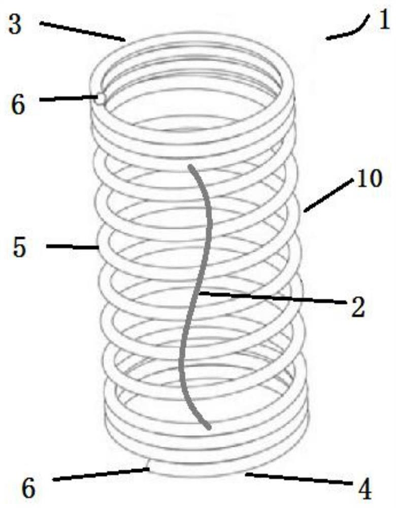
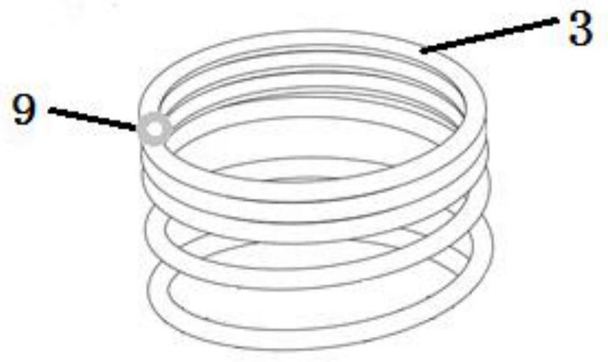
[0025] Such as Figure 1-3 As shown, an adjustable bracket with a buckle structure includes a bracket body 10 with a cavity, and elastic buffer ribs 2 arranged on the bracket body 10. The bracket body 10 is made of a single metal wire or a plurality of Composite metal wire is helically wound, such as elastic metal wire wound around a mold and shaped, it can also be 3D printed from elastic polymer materials, and has two configurations of axial compression and expansion. The buffer ribs 2 are elongated and S-shaped, and are fixed on the outer surface or inner surface of the bracket body 10 by spot welding or bonding. When the bracket is compressed or expanded axially, the buffer ribs 2 are correspondingly Compression or expansion, the buffer ribs 2 are two and symmetrically arranged along the central axis of the bracket, one end of each buffer rib 2 is attached to the first end 3 of the bracket body, and the other end is attached to the second end 4 of the bracket body .

[00...

Embodiment 2

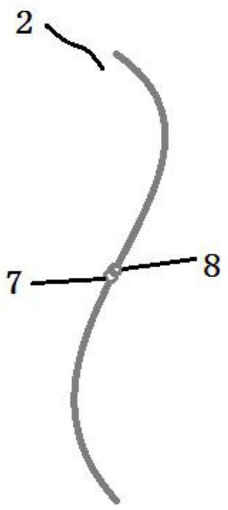
[0034] The structure of this embodiment is basically the same as that of Embodiment 1, the difference is that in this embodiment, each buffer rib 2 is formed into an integrated structure by connecting two elastic material wires end-to-end.

[0035] The end-to-end connection is a buckle connection, wherein one end has a closed buckle structure 7, and the end connected to it has an open buckle structure 8. When connecting, the open buckle structure 8 is inserted into the closed buckle structure 7 along the opening. , and press the opening to become smaller to avoid falling off from the opening. The end-to-end connection can also be welded, glued or socketed.

[0036] The end-to-end connection is the middle part of the elongated S-shaped buffer rib 2, that is, each connected section is a C-shaped structure.

[0037]The combined buffer ribs connected by ring fasteners can meet the sufficient radial support force of the bracket, and can also provide buffer for its expansion and con...


PUM


Abstract

The invention discloses an adjustable stent with a buckle structure. The adjustable stent comprises a stent body with a cavity and elastic buffer ribs arranged on the stent body; the stent body is formed by spirally winding a single metal wire or a plurality of composite metal wires, or is formed by 3D printing of an elastic polymer material, and has an axial compression structure and an axial expansion structure; the buffer ribs are in a slender S shape and are fixed on the outer surface or the inner surface of the stent body in a spot welding or bonding mode; when the stent is axially compressed or expanded, the buffer ribs are correspondingly compressed or expanded along with the stent body; the number of the buffer ribs is two, and the buffer ribs are symmetrically arranged along the central axis of the stent; one end of each buffer rib is attached to the first end of the stent body, the other end of each buffer rib is attached to the second end of the stent body, the first end and the second end of the stent body are arranged more closely than the middle section and are stacked ends formed by tightly winding wires for 2.5 circles; and the slender S-shaped buffer ribs have supporting and buffering effects.

Description

technical field [0001] The invention relates to the technical field of implantable stents in the body, in particular to an adjustable stent with a buckle structure. Background technique [0002] At present, common cardiovascular and cerebrovascular diseases mainly include arterial stenosis, aneurysm, etc. Cardiovascular and cerebrovascular diseases are one of the important causes of human death, and stent intervention is one of the main means of treating cardiovascular diseases, and it is widely used clinically. Vascular stents mainly include bare metal stents and drug-eluting stents. Bare metal stents have achieved remarkable curative effects after entering clinical treatment, but after more than ten years of application, some shortcomings and disadvantages have gradually been exposed, such as prone to thrombosis, high restenosis rate, and damage to vessel walls, etc. Clinical studies have shown that the incidence of in-stent restenosis 6 months after bare metal stent impl...

Claims


Application Information

Patent Timeline
Patent Type & Authority Applications(China)
IPC IPC(8): A61F2/88A61F2/07
CPCA61F2/07A61F2/88A61F2002/075A61F2220/005A61F2220/0058A61F2230/0091
Inventor 赵晓辉
Owner 赵晓辉
Why Eureka
Try Eureka