An orthopedic auxiliary training bed for lumbar disc herniation
A lumbar disc herniation and orthopedic technology, applied in passive exercise equipment, physical therapy, vehicle rescue, etc., can solve the problem of not relaxing the body, squeezing the patient's waist, and supporting the patient's upper body, etc. problem, achieve the effect of improving recovery effect and reducing labor intensity
- Summary
- Abstract
- Description
- Claims
- Application Information
AI Technical Summary
Problems solved by technology
Method used
Image
Examples
Embodiment 1
[0028] An orthopedic auxiliary training bed for lumbar disc herniation, such as Figure 1-4 As shown, it includes a bed frame 1, a bracket 2, a bed board 3, a universal wheel 31, a lifting mechanism 4 and a driving mechanism 5. The front and rear sides of the top of the bed frame 1 are connected with a bracket 2, and the middle of the bed frame 1 slides A bed board 3 is connected, a universal wheel 31 is installed at the bottom of the bed board 3, a lifting mechanism 4 is connected between the brackets 2 on both sides, a driving mechanism 5 is connected between the front bracket 2 and the front side of the bed frame 1, and the driving mechanism 5 is drivingly connected with the holding mechanism 4 .
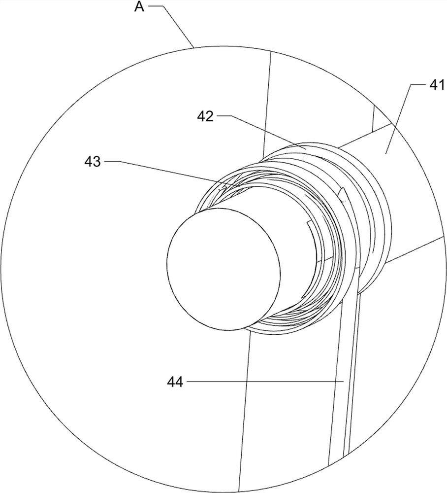
[0029] The lifting mechanism 4 includes a transmission rod 41, a winding disc 42, a scroll spring 43, a first pull wire 44 and a Velcro 45. A transmission rod 41 is rotatably connected between the brackets 2 on both sides. Both sides are connected with a winding reel 42, a scrol...
Embodiment 2
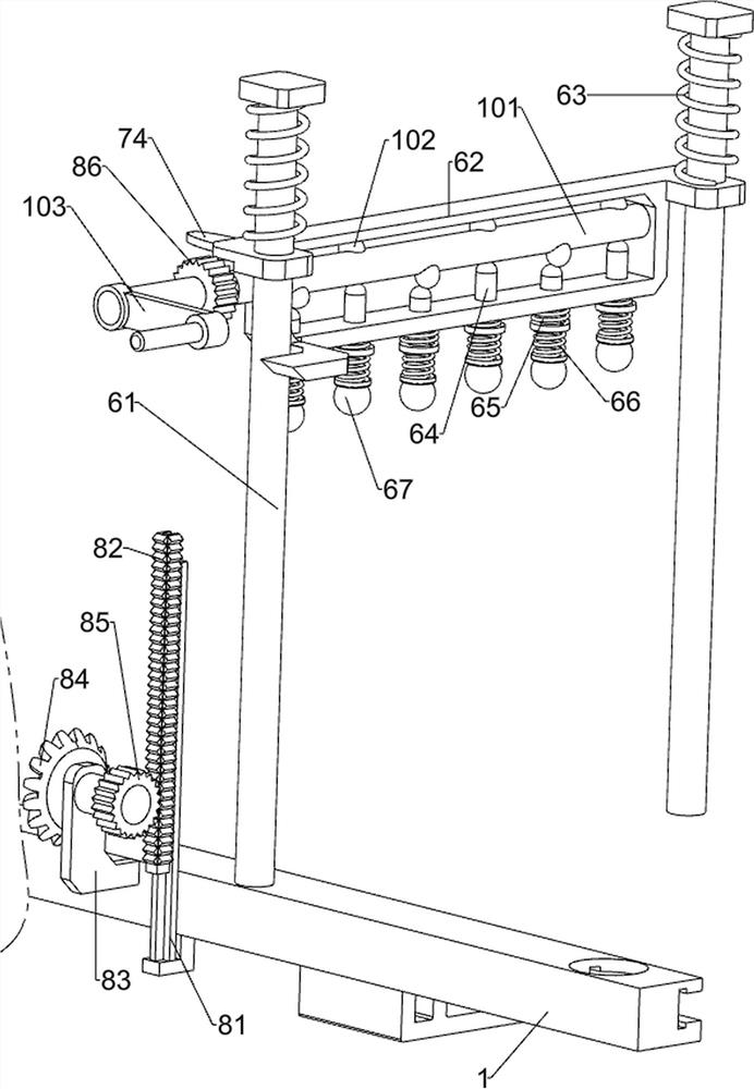
[0033] On the basis of Example 1, as figure 2 and Figure 5As shown, it also includes a waist massage assembly 6, and the waist massage assembly 6 includes a guide rod 61, a sliding frame 62, a first return spring 63, a contact rod 64, a second return spring 65, a third return spring 66 and a hammer ball 67 , the front and rear sides of the middle part of the bed frame 1 are connected with guide rods 61, the guide rods 61 are located on the right side of the bracket 2, and a sliding frame 62 is slidably connected between the guide rods 61 on both sides. The sliding frame 62 and the guide rod 61 A first return spring 63 is connected between the tops, the first return spring 63 is sleeved on the outer side of the guide rod 61 , the bottom of the sliding frame 62 is evenly slidably connected with a contact rod 64 , and a second contact rod 64 is connected between the contact rod 64 and the sliding frame 62 . Two return springs 65 , the bottom end of the contact rod 64 is connec...
Embodiment 3
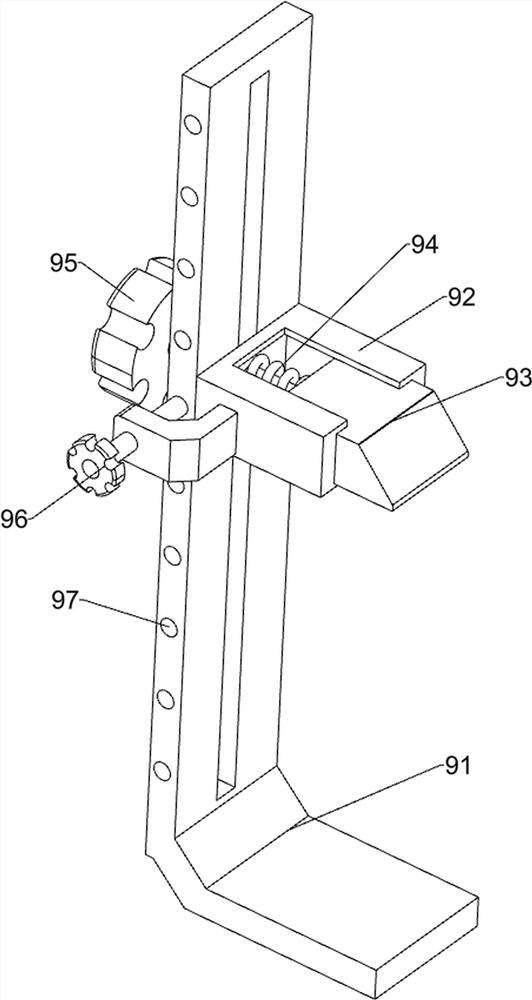
[0038] On the basis of Example 2, as Figure 4-6 As shown, it also includes a clamping mechanism 9. The clamping mechanism 9 includes a mounting frame 91, a sliding sleeve 92, a wedge block 93, an elastic member 94, a first pull rod 95 and a second pull rod 96. The front end of the bed frame 1 is connected with a Mounting frame 91, a sliding sleeve 92 is slidably connected to the mounting frame 91, a wedge-shaped block 93 is slidably connected to the sliding sleeve 92, an elastic member 94 is connected between the wedge-shaped block 93 and the sliding sleeve 92, and the front end of the wedge-shaped block 93 A first pull rod 95 is connected, the right side of the sliding sleeve 92 is slidably connected with a second pull rod 96 , and the right end of the mounting frame 91 is evenly spaced with sockets 97 , which are matched with the second pull rod 96 .
[0039] When the sliding frame 62 moves downward and contacts the wedge-shaped block 93, the sliding frame 62 pushes the wed...
PUM
 Abstract
Description
Claims
Application Information
 - R&D
- Intellectual Property
- Life Sciences
- Materials
- Tech Scout
- Unparalleled Data Quality
- Higher Quality Content
- 60% Fewer Hallucinations
Browse by: Latest US Patents, China's latest patents, Technical Efficacy Thesaurus, Application Domain, Technology Topic, Popular Technical Reports.
© 2025 PatSnap. All rights reserved.Legal|Privacy policy|Modern Slavery Act Transparency Statement|Sitemap|About US| Contact US: help@patsnap.com


