Grinding equipment for mounting plastic plate at bottom of mounting seat

A plastic plate and mounting seat technology, which is applied in grinding/polishing equipment, machine tools suitable for grinding workpiece planes, plastic recycling, etc., can solve the problems of complicated operation and low grinding efficiency, and achieve the effect of simplifying the operation process

Active Publication Date: 2021-08-06
郭涵沫
View PDF10 Cites 4 Cited by
  • Summary
  • Abstract
  • Description
  • Claims
  • Application Information

AI Technical Summary

Problems solved by technology

[0004] In order to overcome the shortcomings of complex operation and low grinding efficiency, technical problems: provide a grinding equipment for plastic plate installed at the bottom of the mounting seat, which reduces the risk factor of workers, automates and simplifies the operation process, and improves the smoothness of grinding

Method used


Image

  • Grinding equipment for mounting plastic plate at bottom of mounting seat
  • Grinding equipment for mounting plastic plate at bottom of mounting seat
  • Grinding equipment for mounting plastic plate at bottom of mounting seat

Examples


Embodiment 1

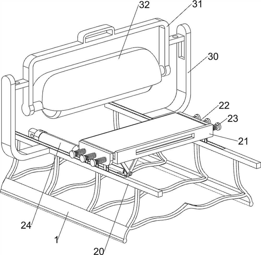
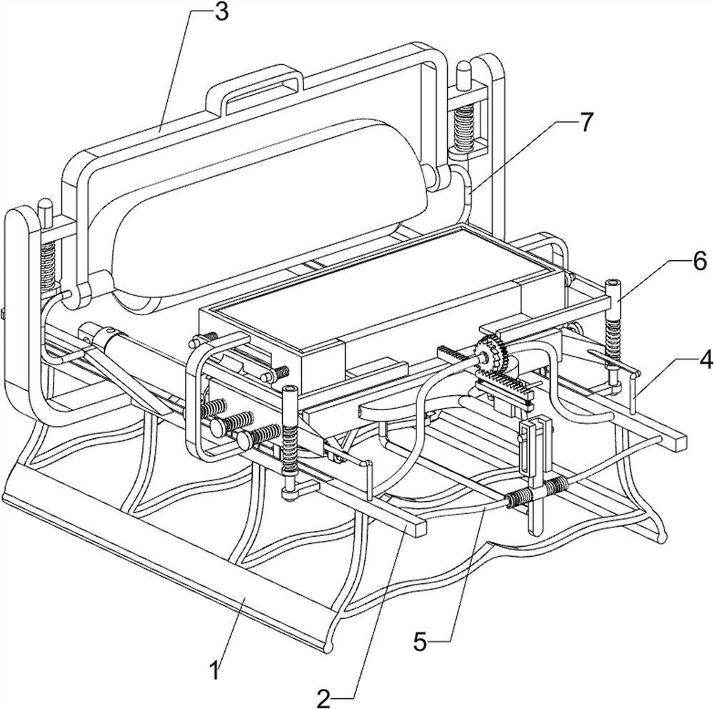
[0066] A kind of grinding equipment for installing plastic plate at the bottom of the mount, such as figure 1 As shown, it includes a base 1 , a clamping mechanism 2 and a grinding mechanism 3 , the upper left and right sides of the base 1 are connected with the clamping mechanism 2 , and the outside of the clamping mechanism 2 is connected with the grinding mechanism 3 .

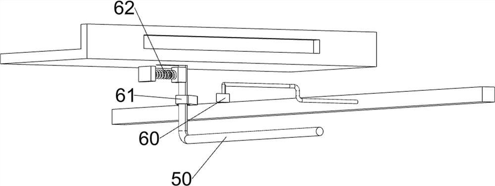
[0067] When the device needs to be used, the user can pull the clamping mechanism 2 to the outside, at this time the clamping mechanism 2 is compressed, and the plastic plate is placed on the clamping mechanism 2, and the clamping mechanism 2 is released, and the clamping mechanism 2 Under the action of resetting, the clamping mechanism 2 is driven to move inwardly to achieve the purpose of clamping the plastic plate and facilitating subsequent operations. At this time, the user can remove the grinding mechanism 3, start the clamping mechanism 2 and the grinding mechanism 3, and clamp The telescopic rod of ...

Embodiment 2

[0069] On the basis of Example 1, such as figure 2 As shown, the clamping mechanism 2 includes a slide rail 20, a discharge plate 21, a clamping block 22 and a first spring 23, the front and rear sides of the upper part of the base 1 are connected with slide rails 20, and the slide rails 20 are slidably connected with The discharge plate 21 is slideably connected with a clamping block 22 on the front and rear sides of the discharge plate 21, a plurality of first springs 23 are wound on the front and rear sides of the discharge plate 21, and the upper side of the base 1 is connected with a cylinder 24. The telescopic link right side of cylinder 24 is connected with discharge plate 21 left sides.

[0070]When the device needs to be used, the user can pull the clamping block 22 to the outside, at this time the first spring 23 is compressed, the plastic plate is placed on the discharge plate 21, the clamping block 22 is released, and the first spring 23 Under the action of reset...


PUM


Abstract

The invention relates to grinding equipment, in particular to grinding equipment for mounting a plastic plate at the bottom of a mounting seat. According to the grinding equipment for mounting the plastic plate at the bottom of the mounting seat, the danger coefficient of workers is reduced, the operation process is automated and simplified, and the grinding smoothness is improved. The grinding equipment for mounting the plastic plate at the bottom of the mounting seat comprises a base, clamping mechanisms and grinding mechanisms, and the clamping mechanisms are connected to the two sides of the top of the base; and the outer sides of the clamping mechanisms are connected with the grinding mechanisms. According to the grinding equipment, through cooperation of a discharging plate, clamping blocks, first springs and an air cylinder, the purpose of grinding the plastic plate is achieved.

Description

technical field [0001] The invention relates to a grinding device, in particular to a grinding device for installing a plastic plate at the bottom of a mounting seat. Background technique [0002] In the daily machining process, in order to make the surface of some metal plates smooth, it needs to be polished. The existing device for grinding the plastic plate installed on the bottom of the mounting seat needs to manually install the plastic plate on the bottom of the mounting seat to fix it. live, which will threaten the physical safety of workers, and the efficiency of grinding is low, and the operation is not flexible enough to meet special grinding needs. [0003] Aiming at the operation of installing plastic plates at the bottom of the mounting base, the present invention develops a grinding equipment for installing plastic plates at the bottom of the mounting base, which reduces the risk factor of workers, automates and simplifies the operation process, and improves th...

Claims


Application Information

Patent Timeline
Patent Type & Authority Applications(China)
IPC IPC(8): B24B7/30B24B41/02B24B47/06B24B41/00B24B41/06
CPCB24B7/30B24B41/02B24B47/06B24B41/005B24B41/06Y02W30/62
Inventor 郭涵沫
Owner 郭涵沫
Why Eureka
Try Eureka