
Worm positioning device

A technology for positioning devices and worms, which is applied in the direction of workpiece clamping devices, workbenches, manufacturing tools, etc., can solve the problems of hard to see the wear of the tooth surface, low inspection efficiency, and the inability to accurately position the worm, and achieve simple structure, Easy to create, precise positioning effect

Pending Publication Date: 2021-08-06
深圳市昱森机电有限公司
View PDF0 Cites 0 Cited by
  • Summary
  • Abstract
  • Description
  • Claims
  • Application Information

AI Technical Summary

Problems solved by technology

[0002] As a commonly used transmission structure, worms often wear on the tooth surface, but it is difficult to see the wear of the tooth surface with the naked eye. The existing way to check the wear of the worm tooth surface is that the operator holds the worm, rotates the worm, and looks at the electronic magnifying glass. Check the tooth surface for wear
However, this method cannot accurately locate the worm, and the inspection efficiency is low

Method used


Image

  • Worm positioning device

Examples


Embodiment Construction

[0021] The technical solutions of the present invention will be further described below in conjunction with the accompanying drawings and embodiments. It should be understood that the specific embodiments described here are only used to explain the present invention, but not to limit the present invention. In addition, it should be noted that, for the convenience of description, only the parts related to the present invention are shown in the drawings but not all of them.

[0022] In the description of the present invention, it should be noted that unless otherwise specified and limited, the terms "installation", "connection" and "connection" should be understood in a broad sense, for example, it can be a fixed connection or a detachable connection. Connection; it can be a mechanical connection or an electrical connection; it can be a direct connection or an indirect connection through an intermediary, and it can be the internal communication of two components. Those of ordin...


PUM


Abstract

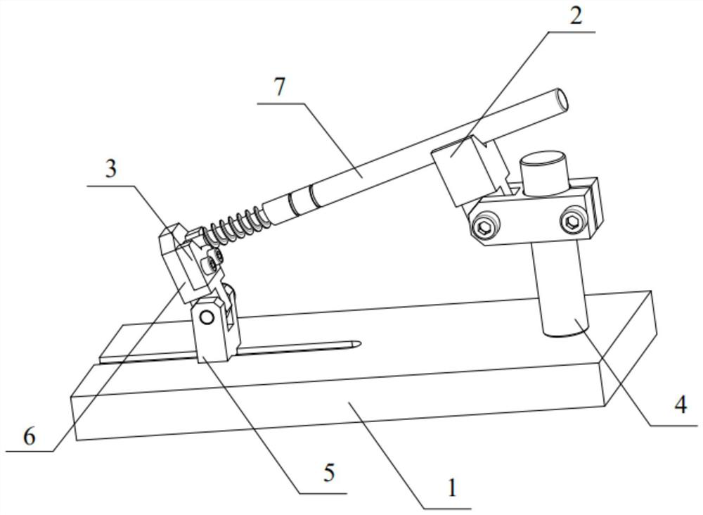
The invention relates to the technical field of worms, in particular to a worm positioning device which comprises a bottom plate, a first fixing block and a second fixing block. The first fixing block and the second fixing block are arranged on the bottom plate in a spaced manner in the first direction and used for supporting a worm to be detected; and the first fixing block and the second fixing block can selectively rotate or be locked relative to the bottom plate, and at least one of the first fixing block and the second fixing block can move in the vertical direction relative to the bottom plate. According to the worm positioning device, by arranging the first fixing block and the second fixing block which can support the worm to be detected, an operator does not need to hold the worm to detect tooth surface abrasion, the first fixing block and the second fixing block can rotate relative to the bottom plate, and therefore the operator can conveniently detect different positions of the worm; and meanwhile, the height difference between the first fixing block and the second fixing block is adjustable, the operator can conveniently incline a to-be-detected screw to form different angles, the device is simple in structure, convenient to manufacture and more accurate in positioning, and the working efficiency is improved.

Description

technical field [0001] The invention relates to the technical field of worms, in particular to a worm positioning device. Background technique [0002] As a commonly used transmission structure, worms often wear on the tooth surface, but it is difficult to see the wear of the tooth surface with the naked eye. The existing way to check the wear of the worm tooth surface is that the operator holds the worm, rotates the worm, and looks at the electronic magnifying glass. Check the tooth surface for wear. However, this method cannot accurately locate the worm, and the inspection efficiency is low. Contents of the invention [0003] The purpose of the present invention is to provide a worm positioning device, which can position the worm without requiring the operator to hold the worm to check the wear of the tooth surface, thereby improving the working efficiency. [0004] For reaching this purpose, the present invention adopts following technical scheme: [0005] A worm pos...

Claims


Application Information

Patent Timeline
Patent Type & Authority Applications(China)
IPC IPC(8): B25B11/00B25H1/16B25H1/18
CPCB25B11/00B25H1/16B25H1/18
Inventor 雷诗琼郭飞虎
Owner 深圳市昱森机电有限公司
Learn More