Undercut removing mechanism of injection mold

An injection mold and upside down technology, applied in the field of tripping mechanism, can solve the problems of low strength, low cost, cumbersome mechanism, etc., and achieve the effects of high product quality, smooth demoulding, and wide application range.

Pending Publication Date: 2021-08-06
ZHEJIANG KAIHUA MOLDS
View PDF5 Cites 3 Cited by
  • Summary
  • Abstract
  • Description
  • Claims
  • Application Information

AI Technical Summary

Problems solved by technology

[0004] The present invention aims to overcome the problems of low structural strength, cumbersome mechanism or low cost of the prior art mold tripping and undercutting, and provides a tripping and undercutting mechanism for injection molds, which ensures the strength of the mold, simplifies the mold structure, reduces the cost of mold manufacturing, and improves Productivity

Method used


Image

  • Undercut removing mechanism of injection mold
  • Undercut removing mechanism of injection mold
  • Undercut removing mechanism of injection mold

Examples


Embodiment 1

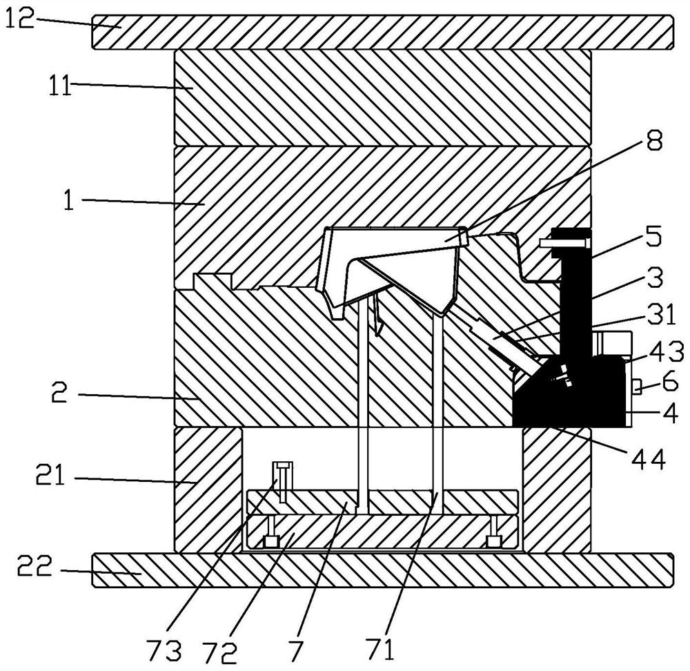
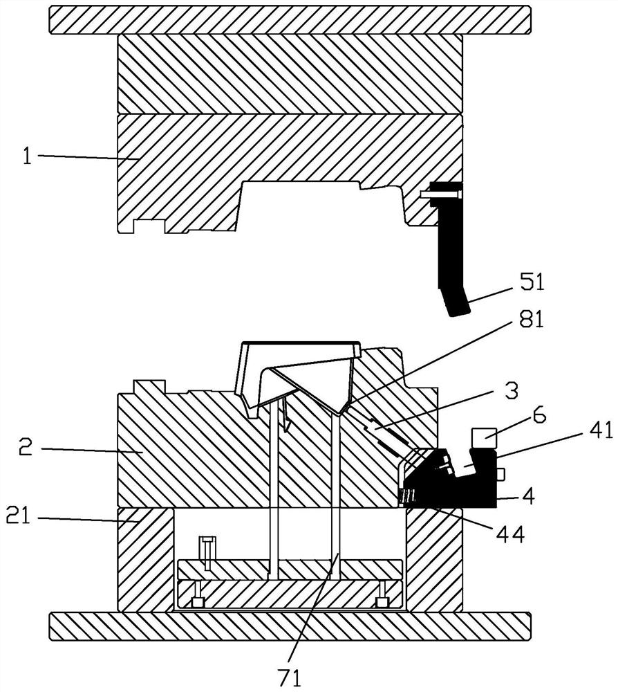
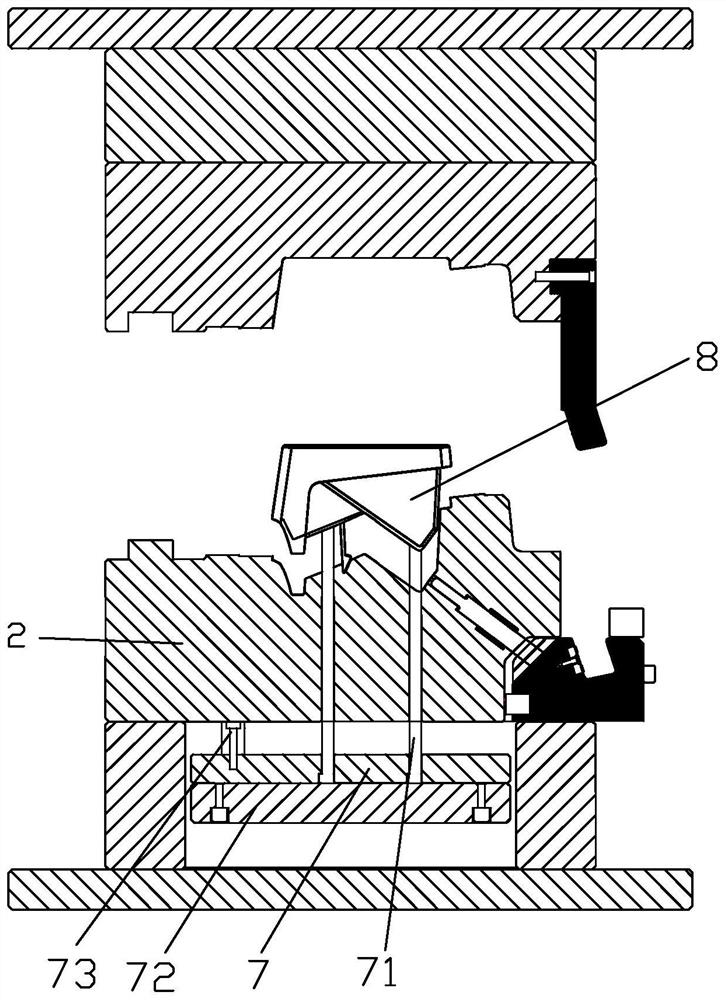
[0041] like figure 1 , figure 2 , image 3 As shown, a detachment mechanism of an injection mold includes:

[0042] The upper web 12 and the lower abdomen 22 are connected below the upper web 12, and the heat flow plate 11 is connected to the heat flow board 11, and the lower abdomen 22 is connected to the lower belt 21, and the surface 21 is connected to the core 2. The core 2 forms a space for injection molding between the core 2 and the cavity 1. The upper pin plate 7 and the lower top needle plate 72 are provided in the space between the core 2 and the lower abdomen 22, and the upper needle plate 7 extends upward, and the top rod 71 extends into the injection space, on the top of the top The protruding limit block 73 is protruding.

[0043]Also included, the chipper 3, the slider 4, the oblique wedge member 5, and the limit piece 6. The oblique wedge 5 integrally a long strip structure having a rectangular cross section, including a clutch wedge 51 at the upper extension 52 and...

Embodiment 2

[0050] like Figure 5 , Image 6 As shown, a detachment mechanism of an injection mold is substantially the same as that of Example 1, and the difference is that the wedge portion 51 includes a plurality of slug 511, and the block 511 is a rectangular structure, including one end block. And several middle plugs. A swallow ridge is provided on one side of the end block, and a dovetail ridge is provided on one side of the middle block, and a dovetail tank is provided on the other side. The socket 511 extends in the direction of the clad wedge portion 51, that is, the lash tank 41 depth direction, adjacent insert 511 is fitted with the slide 41 groove bottom by the tail ridge and the dovetail slot, and the slope 41 groove is provided with the socket 511. Slot 411, slot 411 is a dovetail tank. The diagonal wedge portion 51 length and the depth of the chute 41 are changed by the transfer of the diagonal wedge portion 51 and the chute 41. like Figure 5 As shown, there are two middle slots...


PUM


Abstract

The invention discloses an undercut removing mechanism of an injection mold. The undercut removing mechanism comprises a mold cavity, a mold core, a core-pulling piece, a sliding block and an inclined wedge piece; a space for injection molding of a product is formed between the mold core and the mold cavity; the core-pulling piece can move from a core-pulling mold locking position to a core-pulling demolding position in the mold core; the sliding block is connected to one end, far away from the product, of the core-pulling piece in a sliding manner, and can move from a sliding block mold locking position to a sliding block demolding position, so that the core-pulling piece is driven to move from the core-pulling mold locking position to the core-pulling demolding position; and one end of the inclined wedge piece is fixed to the mold cavity, the other end extends into the sliding block and is matched with the inclined surface of the sliding block, and when the inclined wedge piece is separated from the sliding block, the inclined wedge piece drives the sliding block to move from the sliding block mold locking position to the sliding block demolding position. According to the undercut removing mechanism of the injection mold, the mold strength is guaranteed, the mold structure is simplified, the mold manufacturing cost is reduced, and the production efficiency is improved.

Description

Technical field [0001] The present invention relates to the field of mold, in particular, to a detachment mechanism of an injection mold. Background technique [0002] A large number of plastic parts will usually encounter a reverse buckle when injection molding. Inspose, it is the structure of a "reverse coated" mold, so that the product cannot be smoothly demolded in one direction. Some plastic parts will have some dog's nests due to assembly, and there is a concave mounting hole on the end face of the dog's nest. For such a desired detach buckle structure, the core extraction core or the core is small. The core structure typically includes two kinds, one is a case where the oblique column is combined with the slider. This structure is only suitable for the case where the mounting hole is smaller and the demolded direction angle. If the angle is large, the type is The strength of the core is not guaranteed; the injection mold is not guaranteed; the other core is driven by the c...

Claims


Application Information

Patent Timeline
Patent Type & Authority Applications(China)
IPC IPC(8): B29C45/33B29C45/40B29C45/44
CPCB29C45/33B29C45/4005B29C45/44B29C2045/445
Inventor 李过林连明王永才
Owner ZHEJIANG KAIHUA MOLDS
Why Eureka
Try Eureka