Automatic welding equipment

a welding equipment and automatic technology, applied in the direction of soldering equipment, manufacturing tools, printed circuit manufacturing, etc., can solve the problems of bad short circuit of the circuit board, sputtering phenomenon, etc., and achieve the effect of slowing down the impact strength and reducing the phenomenon of sputtering solder

Inactive Publication Date: 2014-07-31
INVENTEC CORP
View PDF17 Cites 18 Cited by
  • Summary
  • Abstract
  • Description
  • Claims
  • Application Information

AI Technical Summary

Benefits of technology

[0017]A primary technical feature of the automatic welding equipment provided by the present application is that holes are uniformly drilled on the guide plate of the wave soldering machine for guiding the solder to reflow in a staggered manner. Therefore, before the solder flows from an edge of the guide plate to the tank, the solder may directly pass through the holes on the guide plate and fall into the solder tank, which not only may disperse and expand an area in which the solder returns into the tank, but also may slow down an impact strength effectively when the solder fails into the tank, so as to reduce a phenomenon of sputtering the solder and avoid the bad short circuit problem of the circuit board.

Problems solved by technology

However, even if the guide plate has been used in the current wave soldering machine to guide the solder to reflow, when the solder falls into the solder tank from an edge of the guide plate, a sputtering phenomenon may occur as before.
When the solder is sputtered to a face of the circuit board inserted with the electronic element, it often causes a bad short circuit of the circuit board.

Method used


Image

  • Automatic welding equipment
  • Automatic welding equipment
  • Automatic welding equipment

Examples


Embodiment Construction

[0021]A plurality of embodiments of the present application will be disclosed below with reference to drawings. For purpose of clear description, many details in practice will be described together with the following description. However, it should be understood that these details in practice are not used to limit the present application. That is to say, in some embodiments of the present application, these details in practice are unnecessary. Additionally, for purpose of simplifying drawings, some conventional structures and elements in the drawings will he shown in a simple and schematic way.

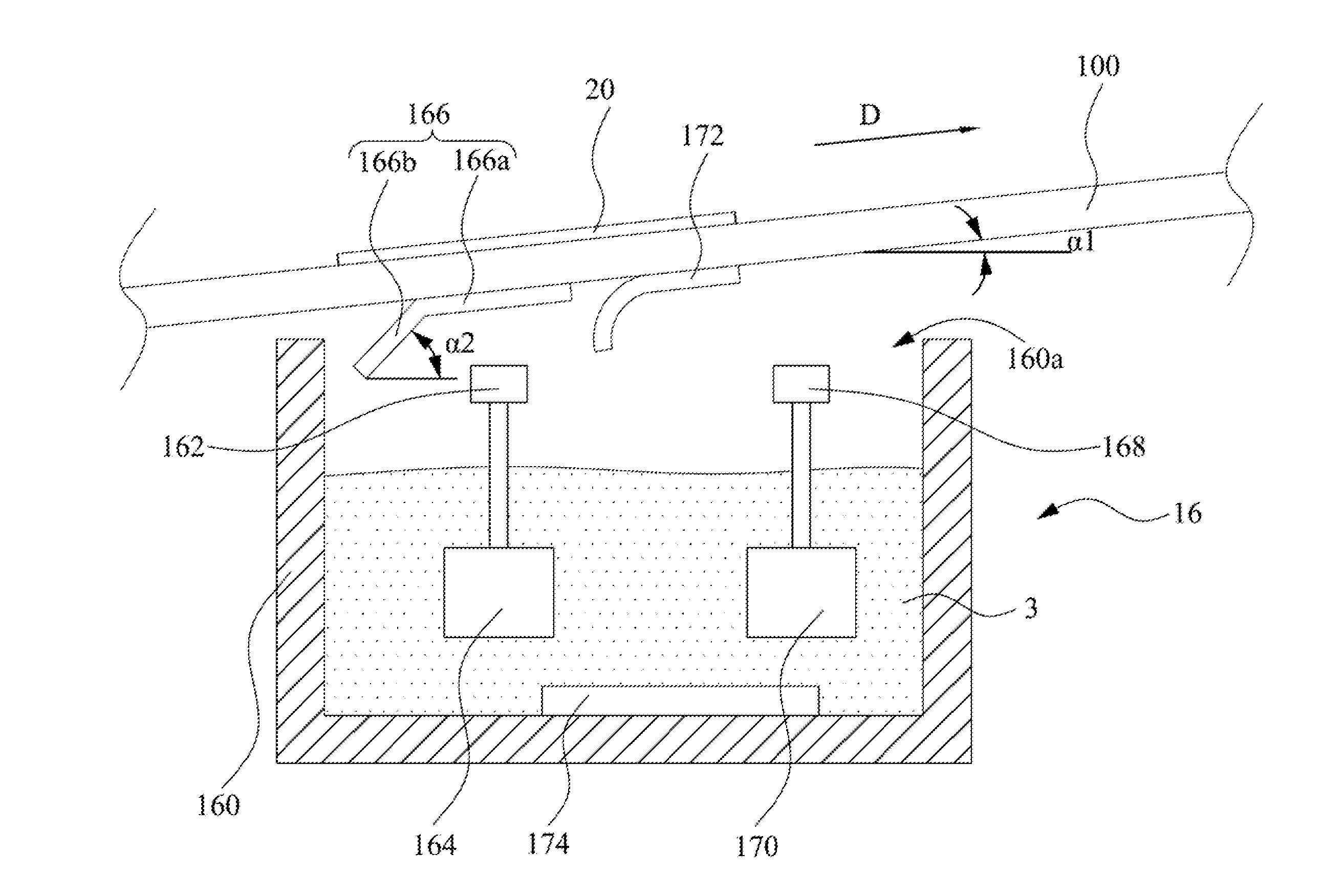
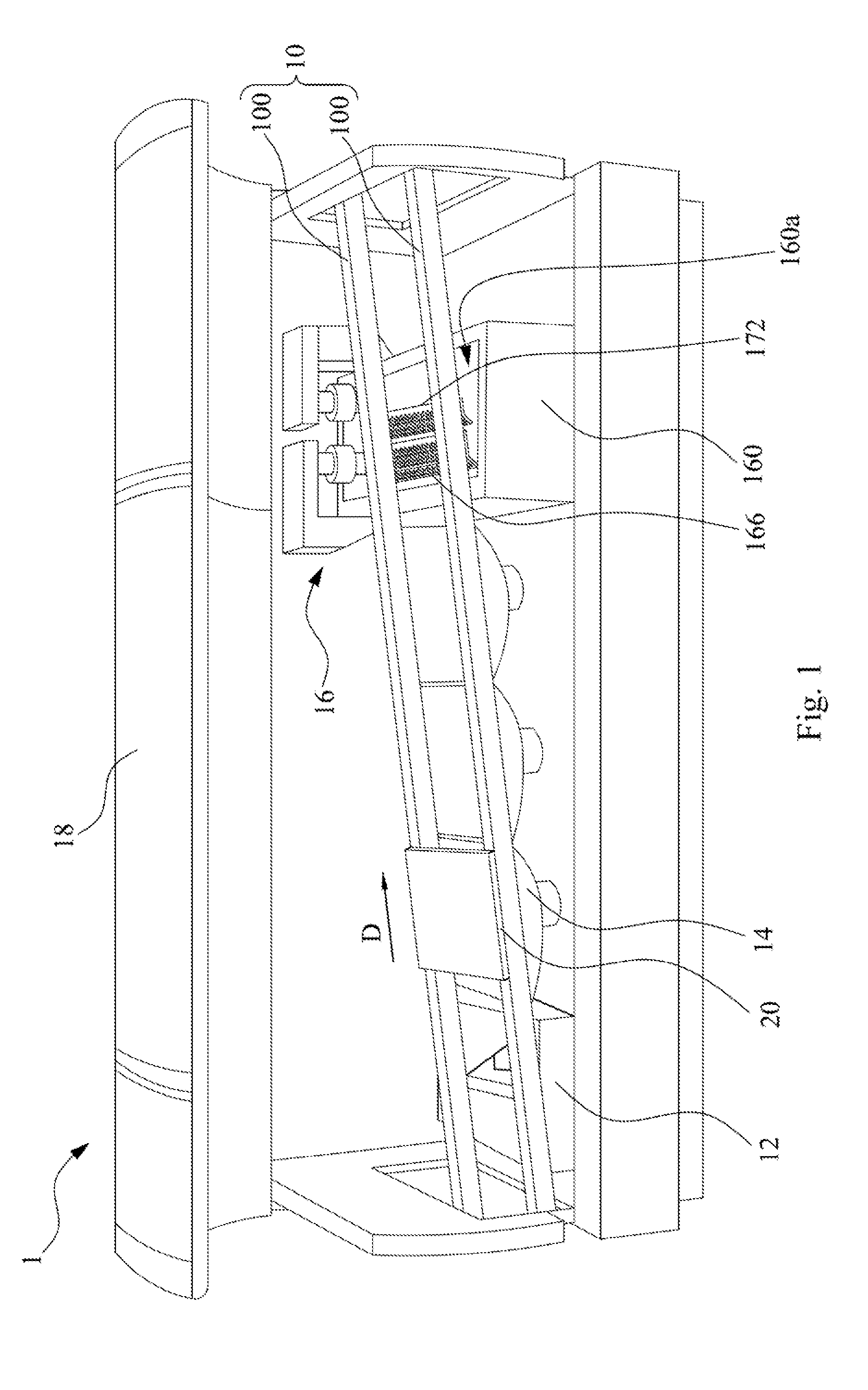
[0022]FIG. 1 is a perspective view depicting automatic welding equipment 1 of an embodiment of the present application.

[0023]As shown in FIG. 1, in the embodiment, the automatic welding equipment 1 includes a conveying mechanism 10, a coating module 12, a preheating module 14, a wave soldering machine 16 and a nitrogen cover glass plate 18. The conveying mechanism 10 of the automatic welding e...


PUM

PropertyMeasurementUnit
slant angleaaaaaaaaaa
slant angle α2aaaaaaaaaa
slant angleaaaaaaaaaa

Abstract

Automatic welding equipment includes a wave soldering machine including a tank, a plurality of first nozzles, a first pump, and a first guide plate. The tank has an opening. The first nozzles and melted solder are disposed in the tank. The first pump is disposed in the tank for jetting the solder via the first nozzles. The first guide plate is located at the opening and includes a first plate portion and a second plate portion. The first plate portion is located over the first nozzles and has a plurality of first holes for passed through by the solder jetted from the first nozzles. The second plate portion, connected to the first plate portion, guides the solder to flow out of the first holes. The solder guided by the second plate portion passes through second holes of the second plate portion and returns into the tank.

Description

RELATED APPLICATIONS[0001]This application claims priority to Taiwanese Application Serial Number 102201767, filed Jan. 25, 2013, which is herein incorporated by reference.BACKGROUND[0002]1. Field of Invention[0003]The present application relates to automatic welding equipment. More particularly, the present application relates to automatic welding equipment including a wave soldering machine.[0004]2. Description of Related Art[0005]A surface mounting technology (SMT) is a welding technology that has been widely used in recent years. Particular equipment is used by the SMT to accurately place a surface mounting component onto a printed circuit board pad which has been subjected to a print welding paste or dispensing, and then a welding process (for example, a wave welding or reflow welding) is made, such that a good mechanical and electrical connection is established between the component and the circuit board. However, a flow process of the current SMT process may be roughly divide...

Claims


Application Information

Patent Timeline
Patent Type & Authority Applications(United States)
IPC IPC(8): B23K3/06
CPCB23K3/0653H05K3/3468B23K3/0646
Inventor HSIEH, CHIN-CHANGMR
Owner INVENTEC CORP
Why Eureka
Try Eureka