[0014] It is therefore an objective of the present invention to solve the above problem and to provide an arrangement structure of an electric junction box, by which the damage of the electric junction box in the event of the collision of the vehicle can be reduced, the deterioration in the collision strength of the battery pack due to a plurality of the notched holes for guiding out the electric wires therethrough can be prevented from occurring, a plurality of the electric wires can be easily connected to the electric junction box with good workability, and a plurality of the electric wires can be easily arranged and protected outside the battery pack.
[0019] With the construction described above, in the event that a vehicle has a collision (a collision at the front or the back of the vehicle), since the electric junction box is arranged on the side of a wall of the battery pack, the wall being situated on a side opposite to a collision side of the vehicle, therefore a shock of the collision is absorbed in a space within the battery pack, thereby preventing the electric junction box from being affected by the direct shock. Accordingly,
high voltage parts and circuits contained in the electric junction box can be prevented from being damaged, thereby preventing a trouble such as a
short circuit from occurring and improving safety of the vehicle. The vehicle is an
electric vehicle including a
hybrid car. The
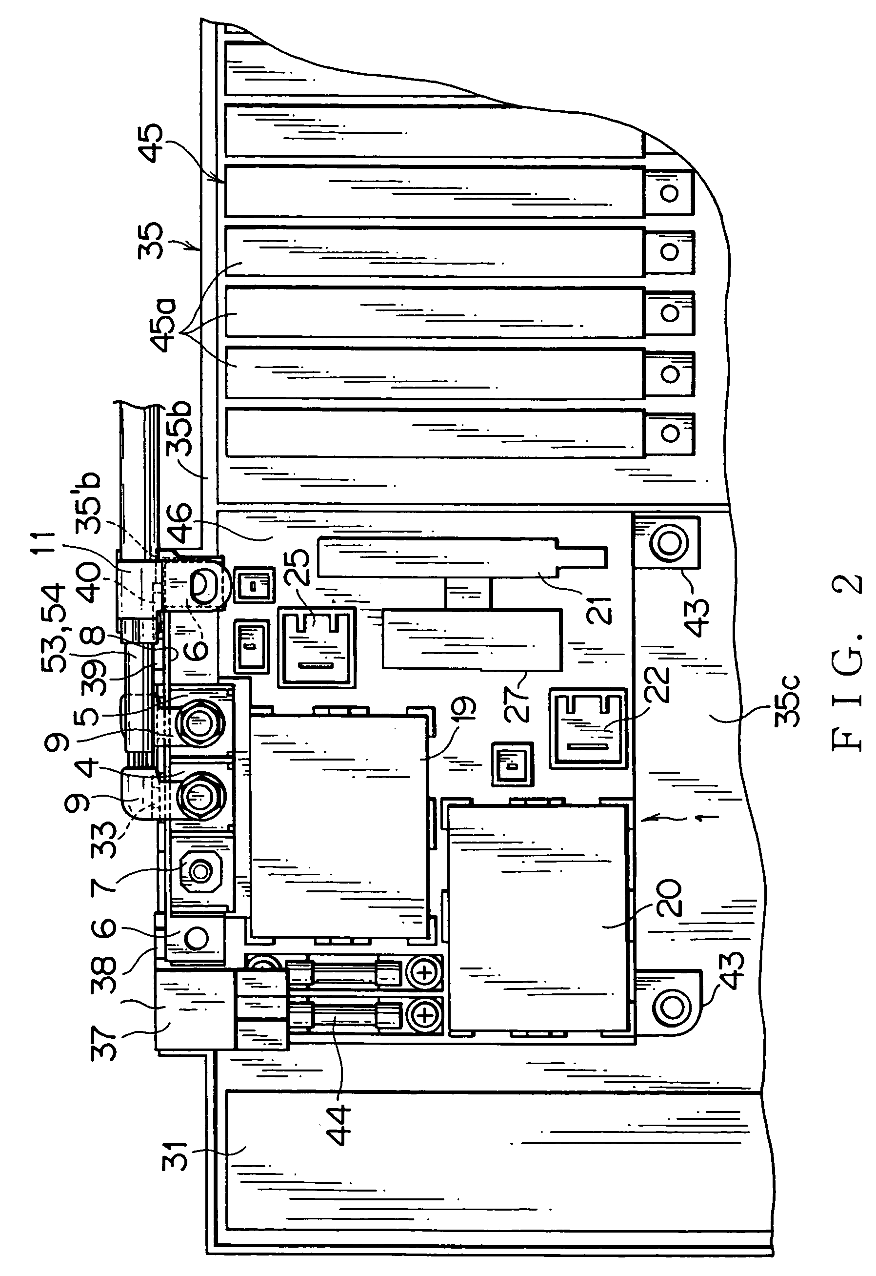
high voltage parts include relays or fuses for connecting or
cutting circuits of a battery and inverter.
[0021] With the construction described above, when the vehicle has a collision, the
electric wire connection parts of the electric junction box can be prevented from being directly damaged and the electric wires guided out from the respective
electric wire connection parts can also be prevented from being directly damaged. Accordingly, safety of a part for guiding out the electric wires of the electric junction box can be secured. Since the electric wires are not guided out into the respective different directions, the deterioration in the strength of the battery pack due to the notched holes for guiding out the electric wires therethrough can be prevented from occurring. The
electric wire connection parts are, for example, connectors or terminal mounts. In the terminal
mount, a terminal of the electric wire is connected by screwing to an end of a
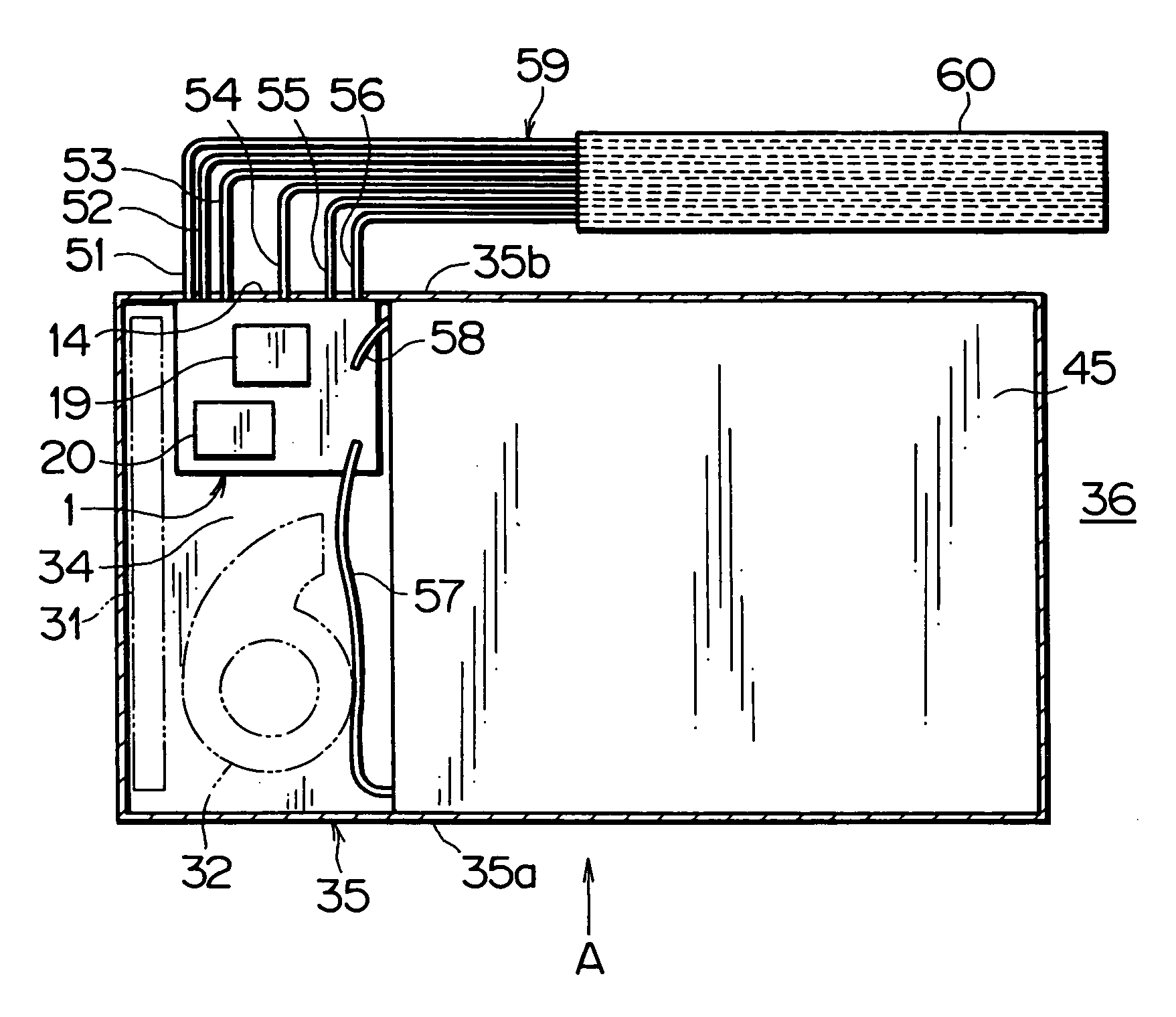
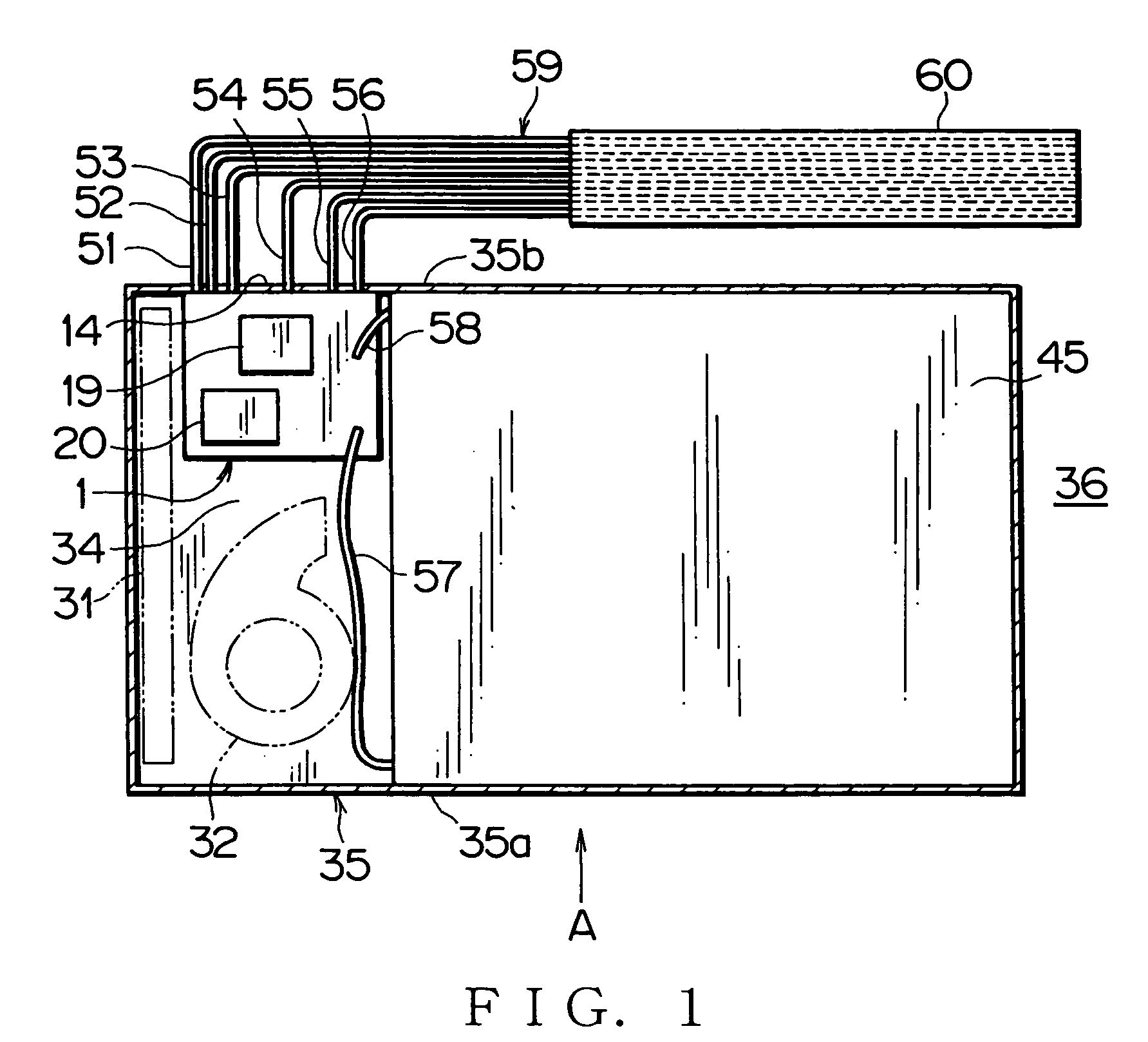
busbar or the like. The respective electric wires are concentratedly connected to the electric junction box on a wall of the battery pack. The connected electric wires are put together and guided out along a wall of the battery pack. Only one protection tube or uniting band is necessary to put the electric wires together as a wiring harness.
[0022] Further, with the construction described above, when the vehicle has a collision, since the electric wire connection parts of the electric junction box can be prevented from being directly damaged, a trouble such as a
short circuit at the electric wire connecting parts can be prevented from occurring, thereby further improving safety of the vehicle. Moreover, since a plurality of the electric wires can be connected to the electric junction box at one place of the battery pack, therefore the connection workability can be improved. Since a plurality of the electric wires can be put together so as to be arranged, therefore the arranging workability can be improved. Since only one electric wire protection tube is needed, therefore the mounting workability of the protection tube can be improved, thereby reducing the cost of the parts.
[0027] With the construction described above, a plurality of the electric wires is concentratedly connected to the electric junction box on a wall of the battery pack. The connected electric wires are put together and guided out along a wall of the battery pack. Only one protection tube or uniting band is necessary to put the electric wires together as a wiring harness. Since the electric wires are not guided out into the respective different directions, the deterioration in the strength of the battery pack due to the notched holes for guiding out the electric wires therethrough can be prevented from occurring. If the wall of the battery pack is set to be a wall situated on a side opposite to a collision side of the vehicle, upon a collision of the vehicle the damage of the electric junction box and the electric wire connecting parts can be reduced.
[0028] Further, with the construction described above, since a plurality of the electric wires can be connected to the electric junction box at one place of the battery pack, therefore the connection workability can be improved. Since a plurality of the electric wires can be put together so as to be arranged, therefore the arranging workability can be improved. Since only one electric wire protection tube is needed, therefore the mounting workability of the protection tube can be improved, thereby reducing the cost of the parts.

