Automatic cap printing equipment for industrial production

A printing and equipment technology, which is applied in the field of automatic hat printing equipment for industrial production, can solve the problems of low work efficiency, time-consuming and laborious printing, etc., and achieve the effect of improving work efficiency and facilitating work

Pending Publication Date: 2021-08-06
陈红
View PDF0 Cites 0 Cited by
  • Summary
  • Abstract
  • Description
  • Claims
  • Application Information

AI Technical Summary

Problems solved by technology

[0004] In order to overcome the time-consuming and labor-intensive and low-efficiency shortcomings of manual printing on hats, the technical problem to be solved is to provide an automatic hat printing equipment for industrial production that can automatically transfer and print hats and has high work efficiency.

Method used


Image

  • Automatic cap printing equipment for industrial production
  • Automatic cap printing equipment for industrial production
  • Automatic cap printing equipment for industrial production

Examples


Embodiment 1

[0024] A kind of cap automatic printing equipment for industrial production, such as figure 1 , figure 2 , image 3 , Figure 4 and Figure 5 As shown, it includes a bottom plate 1, a transport mechanism 2, a stamp mechanism 3, a transmission mechanism 4 and a charging mechanism 5. The transport mechanism 2 is provided on the front side of the top of the bottom plate 1, and the stamp mechanism 3 is provided on the rear side of the top of the bottom plate 1. The right side of the top of the bottom plate 1 A transmission mechanism 4 is arranged on the side, and a charging mechanism 5 is arranged on the transportation mechanism 2 .

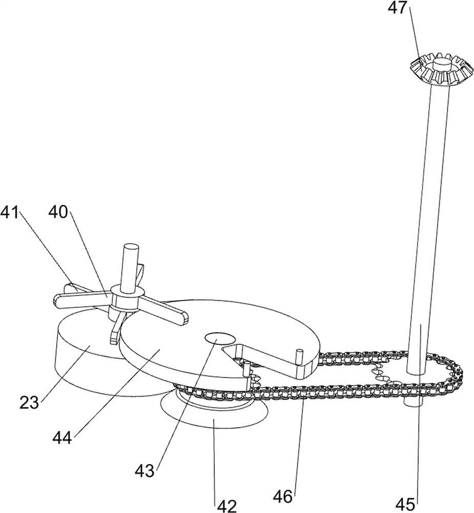
[0025] The transportation mechanism 2 includes a first support plate 20, a first transmission member 21, a second support plate 22, a second transmission member 23, a pulley assembly 24, a driving lever 25 and a support assembly 26, and the left and right sides of the top front side of the bottom plate 1 Two first support plates 20 are provided,...

Embodiment 2

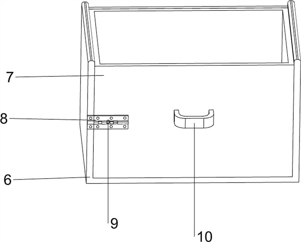
[0031] On the basis of Example 1, such as Figure 6 As shown, it also includes an outer box 6, an inner box 7, a lock 8, a latch 9 and a pull ring 10, the front right part of the bottom plate 1 top is provided with an outer box 6, and the inner box 7 is slidingly provided with the outer box 6, In the middle of the left part of the front side of the inner box 7 and the middle of the left part of the front side of the outer box 6, a lock catch 8 is provided, and a latch 9 is slidably provided on the lock catch 8 on the right side, and the latch 9 cooperates with the lock catch 8 on the left side. A pull ring 10 is provided at the middle part of the front side of the case 7 .

[0032] When people take off the printed hat, they can put the printed hat in the inner box 7, and when all the hats are printed, turn the latch 9 to the right, so that the latch 9 is separated from the left lock 8 , and then pull the pull ring 10 forward, so that the inner box 7, the lock 8 on the right s...


PUM


Abstract

The invention relates to printing equipment, in particular to automatic cap printing equipment for industrial production. The automatic cap printing equipment for industrial production can automatically convey and print caps and is high in working efficiency. The automatic cap printing equipment for industrial production comprises a bottom plate, a conveying mechanism, a seal mechanism, a transmission mechanism and a charging mechanism. The conveying mechanism is arranged on one side of the top of the bottom plate. The seal mechanism is arranged on one side of the top of the bottom plate. The transmission mechanism is arranged on one side of the top of the bottom plate. The charging mechanism is arranged on the conveying mechanism. According to the automatic cap printing equipment for industrial production, through cooperation of the conveying mechanism, the seal mechanism, the transmission mechanism and the charging mechanism, the caps can be automatically conveyed intermittently and automatically printed, and the working efficiency of people is improved.

Description

technical field [0001] The invention relates to a printing device, in particular to an automatic printing device for hats used in industrial production. Background technique [0002] A hat is a piece of clothing worn on the head. It is mainly used to protect the head. Some hats have protruding edges and can also cover the sun. The hat can be used for dressing up, and can also be used to protect hairstyles and cover baldness. Different hats have different characteristics and brands, so people will print on the hats to distinguish different hats and improve the aesthetics of the hats. [0003] In terms of current technology, hats are usually printed manually. At this time, people need to manually pick up the hat and print it, which is time-consuming and laborious, resulting in low work efficiency and low accuracy of manual printing on hats. , It is easy to print the wrong position. To solve the above problems, an automatic hat printing equipment for industrial production that...

Claims


Application Information

Patent Timeline
Patent Type & Authority Applications(China)
IPC IPC(8): B41K3/04B41K3/62
CPCB41K3/04B41K3/62
Inventor 陈红
Owner 陈红
Why Eureka
Try Eureka