Rice cake forming and printing equipment
A printing and equipment technology, which is applied in the field of rice cake forming printing equipment, can solve the problems of slow printing speed and achieve the effect of tight printing
- Summary
- Abstract
- Description
- Claims
- Application Information
AI Technical Summary
Problems solved by technology
Method used
Image
Examples
Embodiment 1
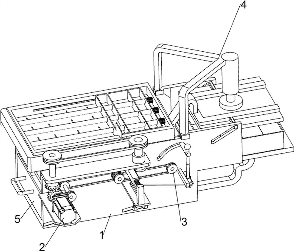
[0024] A kind of rice cake forming printing equipment, such as figure 1 As shown, it includes an installation box 1, a printing mechanism 2 and a transmission mechanism 3. The installation box 1 is provided with a printing mechanism 2, and the installation box 1 is provided with a transmission mechanism 3. The printing mechanism 2 cooperates with the transmission mechanism 3.
[0025] When the user needs to print the formed rice cake, this equipment can be used. First, place the formed rice cake in the installation box 1, then pour flour on the printing mechanism 2, and evenly print the rice cake through the printing mechanism 2 The flour is spread evenly on the rice cake, and the flour on the rice cake is printed simultaneously, and then the rice cake that has been printed is removed by the conveying mechanism 3 .
Embodiment 2
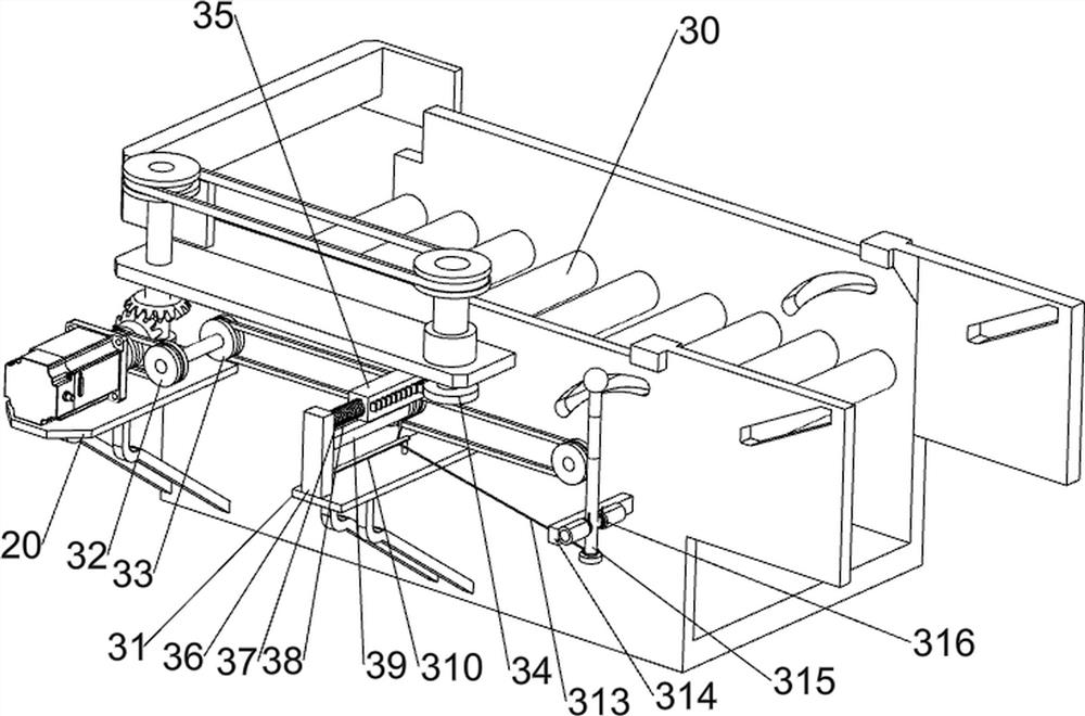
[0027] On the basis of Example 1, such as Figure 2-5 As shown, the printing mechanism 2 includes a first support plate 20, a servo motor 21, a first bearing seat 22, a bevel gear set 23, a first rotating shaft 24, a second supporting plate 25, a second bearing seat 26, and a second rotating shaft 27 , the first pulley assembly 28, shifting block 29, printing mold 210, guide rod 211, first spring member 212 and pushing sub-plate 213, the left side of the installation box 1 front is provided with the first support plate 20, the first support plate 20 top is provided with servomotor 21, and first support plate 20 top rear side is provided with first bearing seat 22, and first bearing seat 22 is provided with first rotating shaft 24 in rotation, and first rotating shaft 24 and the output shaft of servo motor 21 A bevel gear set 23 is connected between them. A second support plate 25 is provided on the upper side of the front of the installation box 1. The first rotating shaft 24 ...
Embodiment 3
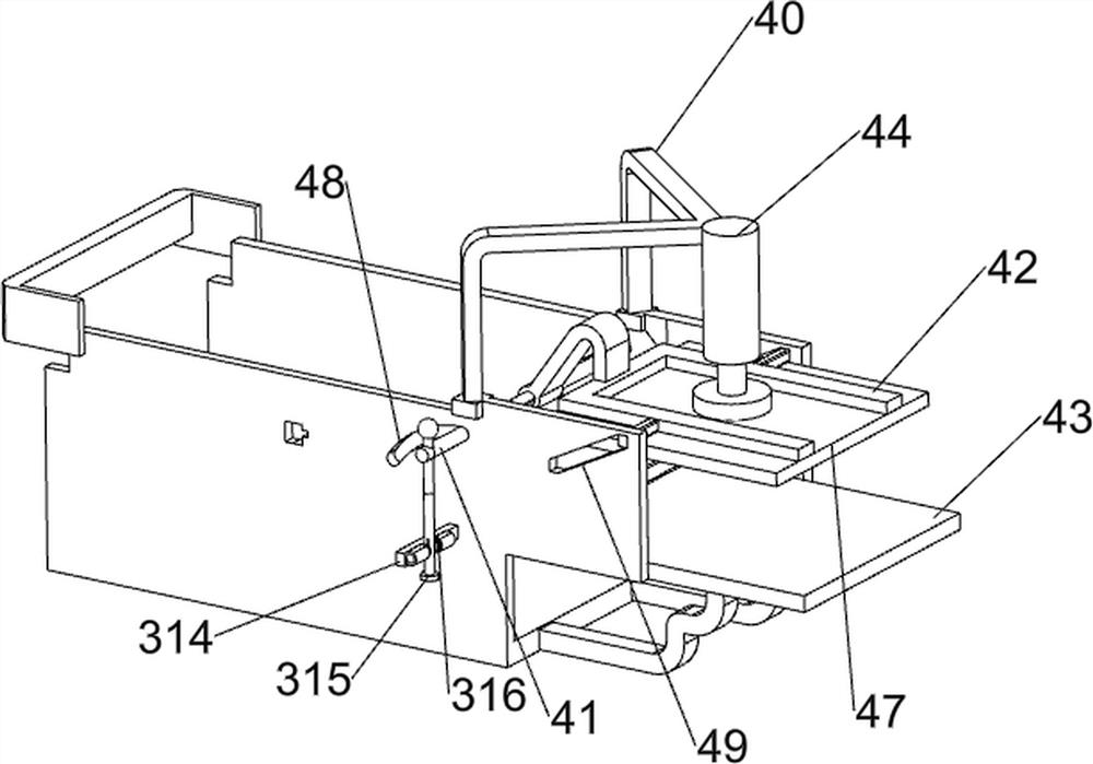
[0032] On the basis of Example 2, such as Figure 5-7 As shown, it also includes a smoothing mechanism 4, the installation box 1 is provided with a smoothing mechanism 4, and the smoothing mechanism 4 includes a fixed frame 40, a first slide bar 41, a pressing block 42, a fourth support plate 43, a sleeve Rod 44, the fourth spring member 45, the second slide bar 46 and pressing plate 47, the right side of installation box 1 top is provided with fixed mount 40, and fixed mount 40 right is provided with sleeve rod 44, and the inner top of sleeve rod 44 is provided with the first Four spring parts 45, sliding type is provided with the second slide bar 46 in sleeve bar 44, and the second slide bar 46 is connected with the 4th spring part 45, and the second slide bar 46 bottom is provided with pressing plate 47, installs box body 1 right bottom A fourth support plate 43 is provided, and the fourth support plate 43 is located below the pressure plate 47. The right side of the instal...
PUM
 Abstract
Description
Claims
Application Information
 - R&D
- Intellectual Property
- Life Sciences
- Materials
- Tech Scout
- Unparalleled Data Quality
- Higher Quality Content
- 60% Fewer Hallucinations
Browse by: Latest US Patents, China's latest patents, Technical Efficacy Thesaurus, Application Domain, Technology Topic, Popular Technical Reports.
© 2025 PatSnap. All rights reserved.Legal|Privacy policy|Modern Slavery Act Transparency Statement|Sitemap|About US| Contact US: help@patsnap.com


