
Energy-saving and environment-friendly industrial sewage treatment equipment

A technology for industrial sewage and treatment equipment, applied in water/sewage treatment equipment, water/sewage treatment, water/sewage multi-stage treatment, etc., can solve the problems of inability to filter impurities and automatic feeding

Active Publication Date: 2021-08-06
金山环保集团有限公司
View PDF6 Cites 5 Cited by
  • Summary
  • Abstract
  • Description
  • Claims
  • Application Information

AI Technical Summary

Problems solved by technology

[0005] In order to overcome the shortcomings of the existing technology that it cannot automatically unload materials and filter impurities, the technical problem is to provide an energy-saving and environmentally friendly industrial sewage treatment equipment that can automatically unload materials and filter impurities.

Method used


Image

  • Energy-saving and environment-friendly industrial sewage treatment equipment
  • Energy-saving and environment-friendly industrial sewage treatment equipment
  • Energy-saving and environment-friendly industrial sewage treatment equipment

Examples


Embodiment 1

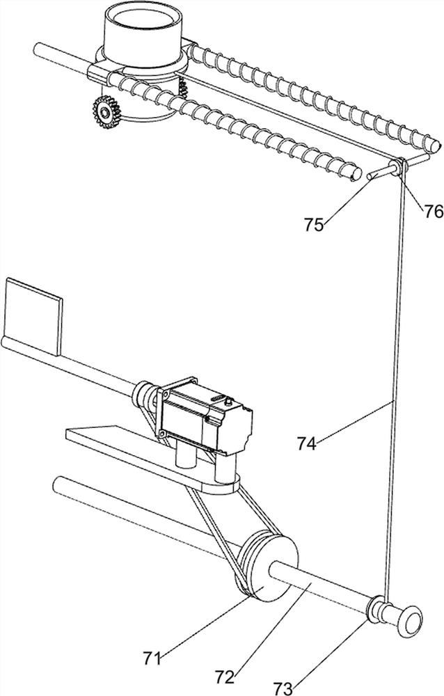
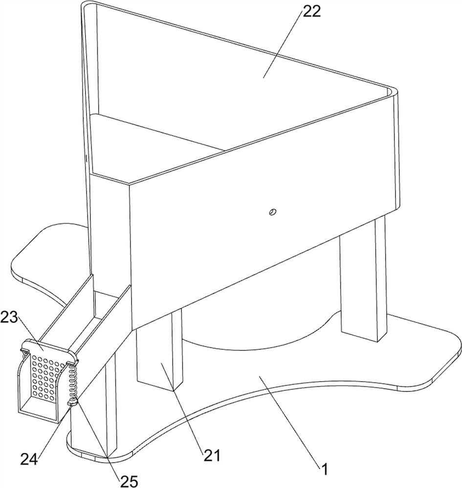
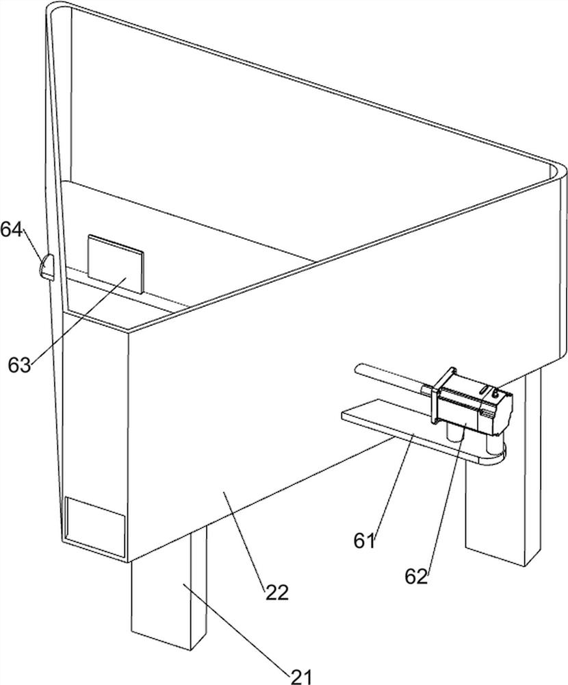
[0028] A kind of energy-saving and environment-friendly industrial sewage treatment equipment, such as figure 1 , figure 2 and image 3 As shown, it includes a base 1 , a transport mechanism 2 and a blanking mechanism 3 , the top of the base 1 is provided with a transport mechanism 2 , and the upper part of the transport mechanism 2 is provided with a blanking mechanism 3 .

[0029] Transport mechanism 2 includes support 21, collection frame 22, filter screen 23, adhesive block 24 and first spring 25, base 1 top is provided with four supports 21, is provided with collection frame 22 between support 21, and collection frame 22 front The side sliding type is provided with a filter screen 23, and the left and right sides of the front part of the collection frame 22 are provided with adhesive blocks 24, and a first spring 25 is arranged between the adhesive block 24 and the filter screen 23.

[0030] The blanking mechanism 3 includes a support frame 31, a limit block 32, a firs...

Embodiment 2

[0033] On the basis of Example 1, such as Figure 4 , Figure 6 , Figure 7 and Figure 8 As shown, the filter assembly 4 is also included, and the filter assembly 4 includes a support rod 41, a connecting block 42, a rack 43, a guide rod 44, a second spring 45, a sliding sleeve 46, a filter frame 47, a first rotating shaft 48, a screen Net 49, gear 410 and torsion spring 411, base 1 top is left and right symmetrically provided with support bar 41, and support bar 41 upper inner side and collecting frame 22 upper part outer sides are symmetrically provided with connection block 42, and support bar 41 tops are all provided with two racks 43, guide rods 44 are symmetrically arranged between the support rods 41, and the guide rods 44 are slidably connected with the first slide bar 33 on the front side, and the left and right symmetrical sliding types between the guide rods 44 are provided with sliding sleeves 46, and the sliding sleeves 46 are connected to the support A second...


PUM


Abstract

The invention relates to treatment equipment, in particular to energy-saving and environment-friendly industrial sewage treatment equipment. The technical problem is to provide the energy-saving and environment-friendly industrial sewage treatment equipment capable of automatically discharging and filtering impurities. According to the technical scheme, the energy-saving and environment-friendly industrial sewage treatment equipment comprises a base, a conveying mechanism and a discharging mechanism; the conveying mechanism is arranged on the top of the base, and the discharging mechanism is arranged on the conveying mechanism. According to the equipment, the effects of automatic discharging and impurity filtering can be achieved; by starting a servo motor, when an output shaft of the servo motor drives a sliding sleeve to move rightwards, the sliding sleeve can drive a first sliding rod to move rightwards, the first sliding rod does not block an outlet of a liquid medicine tank any more, liquid medicine can flow into a collecting frame, and the effect of automatic discharging is achieved.

Description

technical field [0001] The invention relates to a treatment device, in particular to an energy-saving and environment-friendly industrial sewage treatment device. Background technique [0002] Sewage treatment is widely used in construction, agriculture, transportation and energy. It is divided into domestic sewage treatment and production sewage treatment. Nowadays, due to the increasing water pollution, the sewage treatment and regeneration industry has received unprecedented attention. [0003] However, in the process of sewage treatment in the prior art, if the sewage is no longer fully reacted after the potion is used, the material cannot be automatically unloaded, and the prior art cannot filter impurities when treating sewage, so that the treated sewage There is still the phenomenon of impurities floating, which requires people to manually salvage. [0004] In view of the problems existing in the above-mentioned prior art, it is necessary to design an energy-saving a...

Claims


Application Information

Patent Timeline
Patent Type & Authority Applications(China)
IPC IPC(8): C02F9/04
CPCC02F1/00C02F1/001C02F2201/002C02F2201/004C02F2301/08C02F2303/14C02F2303/16
Inventor 刘奕芳
Owner 金山环保集团有限公司
Learn More