
Device for testing performance of aerostat capsule pull tab and test method thereof

A testing device and aerostat technology, applied in the testing of machine/structural components, measuring devices, testing of mechanical components, etc., can solve the problems of inconvenient movement, use, complicated operation, hidden danger of internal gas, etc., and achieve simple installation. , Easy to operate, precise control of the effect of pulling force

Active Publication Date: 2021-08-06
XIANGTAN UNIV +2
View PDF7 Cites 0 Cited by
  • Summary
  • Abstract
  • Description
  • Claims
  • Application Information

AI Technical Summary

Problems solved by technology

The internal gas has certain potential safety hazards, and it is not convenient to move and use under complex conditions
There are problems such as high requirements for capsule sealing, harsh operating conditions, complicated operations, and potential safety hazards

Method used


Image

  • Device for testing performance of aerostat capsule pull tab and test method thereof
  • Device for testing performance of aerostat capsule pull tab and test method thereof
  • Device for testing performance of aerostat capsule pull tab and test method thereof

Examples


Embodiment 1

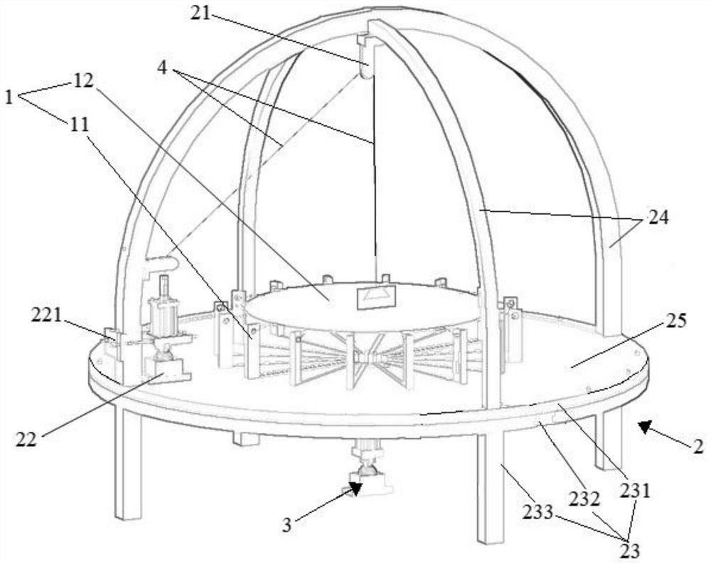
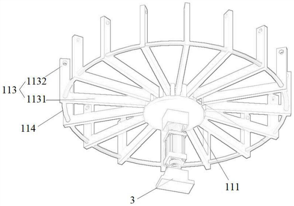
[0099] Such as figure 1 As shown, a test device for the tab performance of the aerostat capsule includes an inner body 1 , an outer frame 2 and a main body load-bearing mechanism 3 . The inner body 1 includes an umbrella frame 11 and a base cloth carrier 12 . The umbrella frame 11 is arranged inside the outer frame 2 . The base fabric carrier 12 is arranged inside the umbrella frame 11 . The main load-bearing mechanism 3 is arranged below the base fabric carrier 12 . The base fabric carrier 12 is provided with a pull tab 4 . The outer frame 2 is provided with a pulley 21 and a force-measuring loading mechanism 22 . The pull tab 4 is connected with the force-measuring loading mechanism 22 through the fiber rope 41 and the pulley 21 .

Embodiment 2

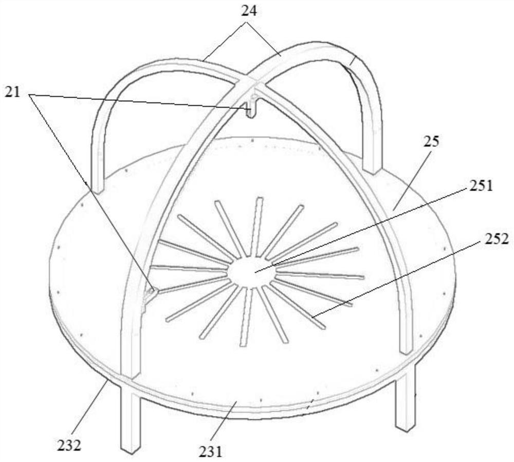
[0101] Embodiment 1 is repeated, except that the outer frame 2 further includes a ring frame support 23 , an arc track beam 24 and an operating table 25 . The curved track beam 24 is designed as an upward convex arc, and both ends of the curved track beam 24 are movably connected to the ring frame support 23 . The operating table 25 is fixedly arranged in the ring of the ring frame support 23 . The pulley 21 is arranged in the arc track beam 24 and can move on the arc track beam 24 .

Embodiment 3

[0103] Embodiment 2 is repeated, except that the outer frame 2 includes a plurality of arc-shaped track beams 24 . The plurality of arc track beams 24 intersect at the beam tops, and the intersection points at the beam tops of the plurality of arc track beams 24 are located on the same vertical line as the ring center of the ring frame support 23 . The pulley 21 can move arbitrarily on several arc track beams 24 .


PUM


Abstract

The invention discloses a device for testing the performance of an aerostat capsule pull tab. The device comprises an inner main body, an outer frame and a main body bearing force loading mechanism. The inner main body comprises an umbrella-shaped framework and a base cloth carrier. The umbrella-shaped framework is arranged in the outer frame. The base cloth carrier is arranged in the umbrella-shaped framework. The main body bearing force loading mechanism is arranged below the base cloth carrier. A pull tab is arranged on the base cloth carrier. The outer frame is provided with a pulley and a force measurement loading mechanism. The pull tab is connected with the force measurement loading mechanism through a towrope and a pulley. The device has the advantages of being easy to install, convenient and fast to operate, capable of rapidly replacing test pieces and the like, meanwhile, multi-angle pulling force can be effectively applied, the pulling force can be accurately controlled, and multiple control modes of force and displacement and multiple modes of static load, dynamic load, periodic load and the like are integrated.

Description

technical field [0001] The invention relates to a technique for testing the mechanical properties of an aerostat capsule structure, in particular to a test device and a testing method for the performance of a tab of an aerostat capsule, and belongs to the technical field of testing the mechanical properties of the aerostat capsule structure. Background technique [0002] Similar to balloons floating in the sky, use a string to hold the balloon. The balloon is called an aerostat, the surface of the balloon is a capsule structure called a base cloth, the rope is called an accessory, and the small part where the balloon is connected to the rope is called a pull tab (node). Since the balloon (aerostat) is not oriented when floating in the air, the angle at which the balloon is connected to the rope (capsule and attachment) changes dynamically. Big or small, fast or slow wind blowing), so the bearing capacity of the pull tab here is different in different states. Traditional te...

Claims


Application Information

Patent Timeline
IPC IPC(8): G01M9/06G01M13/00
CPCG01M9/06G01M13/00
Inventor 陈俊李杰许福杨才千
Owner XIANGTAN UNIV
Learn More