A kind of manipulator unloading brick gripper and unloading method

A technology of manipulator and gripper, which is applied in the field of manipulator unloading brick gripper and brick unloading, which can solve the problems of large power stroke, product falling off, deformation, adhesion, etc.

Active Publication Date: 2022-08-02
洛阳腾和达智能装备有限公司
View PDF0 Cites 0 Cited by
  • Summary
  • Abstract
  • Description
  • Claims
  • Application Information

AI Technical Summary

Problems solved by technology

[0002] In the automatic production process of sintered bricks, the finished bricks are dried and roasted in a tunnel kiln to become finished bricks. During the roasting process, a series of physical and chemical changes will occur, resulting in various deformations, Adhesion, etc., put forward higher requirements for the later stacking and unloading process. Not only must the clamping be reliable, but more importantly, the clamp must first enter the various air ducts of the brick stack, and then the stacking and unloading clamping can be performed. Therefore, the gripper The structure directly affects the reliability and applicability of the grasping, and the unreasonable structure will cause insufficient clamping space, deviation of the grasping position, and product fall-off, etc.
[0003] The structure of the existing brick unloading gripper for manipulators consists of inner clips, outer clips, guide mechanisms, power mechanisms and other related parts. The inner clips and outer clips move horizontally through the guide mechanism and power mechanism. The piece first moves to clamp the lower brick, and then the inner clamp moves to clamp the upper brick, so that the upper and lower bricks are separated to realize the clamping and unloading. The disadvantages are that the structure of the gripper is complicated, the power stroke is large, and it takes up a lot of space. , the separation effect of the upper and lower bricks is not ideal

Method used


Image

  • A kind of manipulator unloading brick gripper and unloading method
  • A kind of manipulator unloading brick gripper and unloading method
  • A kind of manipulator unloading brick gripper and unloading method

Examples


Embodiment Construction

[0029] The present invention will be described in further detail below in conjunction with the accompanying drawings and embodiments, but not as a basis for any limitation of the invention.

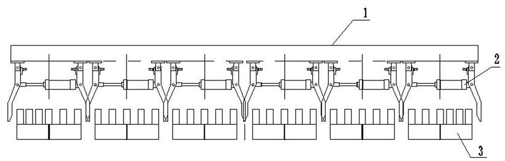
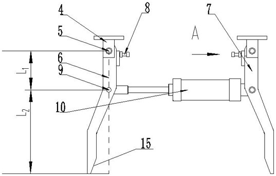
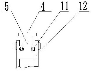
[0030] Referring to the drawings, a manipulator unloading brick gripper, installed on the unloading manipulator, used for the clamping of brick groups 3 on the brick stack, includes a plurality of swing claws arranged on the lower surface of the manipulator hanger 1 according to the brick stack Combination 2. A plurality of swing claw assemblies 2 are sequentially installed on the manipulator in the same direction to form a row of swing claw assemblies. The manipulator is provided with multiple rows of swing claw assemblies. Among the multiple rows of swing claw assemblies, at least two are a pair. They are clamped in two different positions on the same opposite side of the brick group. The swing claw combination 2 includes a swing claw I6, a swing claw II7 and two hinge supports 4. The u...


PUM


Abstract

A brick unloading gripper for a manipulator and a method for unloading bricks. The unloading brick gripper comprises a plurality of swing claw combinations, the plurality of swing claw assemblies are sequentially installed on a manipulator to form a row of swing claw assemblies, and the manipulator is provided with multiple rows of swing claw combinations Combination; the swing claw combination includes swing claw I, swing claw II and two hinge supports. The upper ends of swing claw I and swing claw II are respectively connected to the manipulator through a hinge support. The connection point between the connected hinge supports is the rotation fulcrum, the two ends of the linear drive mechanism are hinged with the power fulcrum of the swing claw I and the swing claw II respectively, and the distance between the rotation fulcrum and the power fulcrum is L. 1 , the distance between the power fulcrum and the lower edge of the clamping slope on the swing claw is L 2 , and 5L 1 ≥L 2 ≥2L 1 ; The center distance of the two hinge supports is equal to the width before the brick group is clamped, and the spacing between the clamping slopes of the two swing claws is greater than the center distance of the two hinge supports. The invention has the characteristics of simple structure and reliable clamping, and can adapt to the narrow air duct space between the brick stacks.

Description

technical field [0001] The invention belongs to the technical field of sintered brick production equipment, in particular to a brick unloading gripper and a brick unloading method by a manipulator. Background technique [0002] In the automatic production process of sintered bricks, the finished bricks are dried and baked in a tunnel kiln to become finished bricks. During the baking process, a series of physical and chemical changes will be experienced, so that the baked brick stacks will appear various deformations, Adhesion, etc., put forward higher requirements for the later stacking and unloading process. Not only must the gripping be reliable, but more importantly, the gripper must first enter the various air ducts of the brick stack, and then the stacking and unloading can be carried out. Therefore, the gripper The structure directly affects the reliability and applicability of grasping, and an unreasonable structure will cause insufficient grasping space, deviation of...

Claims


Application Information

Patent Timeline
Patent Type & Authority Patents(China)
IPC IPC(8): B65G7/12B25J15/00B25J15/10
CPCB65G7/12B25J15/00B25J15/10
Inventor 闫红星焦妤林孔海燕李华桥赵季甲
Owner 洛阳腾和达智能装备有限公司
Why Eureka
Try Eureka