Elevator suspended ceiling and elevator car roof

An elevator and ceiling technology, applied in the field of elevator cars, can solve the problems of high pressure on passengers, difficult cleaning and operation, and achieve the effect of low-cost replacement, improving overall comfort, and meeting space requirements

Pending Publication Date: 2021-08-10
MITSUBISHI ELECTRIC SHANGHAI ELECTRIC ELEVATOR
View PDF2 Cites 0 Cited by
  • Summary
  • Abstract
  • Description
  • Claims
  • Application Information

AI Technical Summary

Problems solved by technology

When the elevator car space is very narrow, the structure has many defects
First, the elevator is a professional equipment, and the installation and disassembly of the lighting panels requires professionals to operate. If there is no fault, professional maintenance personnel will not actively clean the car environment; and due to the limited area of ​​the car, the current installation method of the lighting panels It is difficult to operate in the car; second, the existing elevator ceiling, in the usual maintenance, because the frame for installing the lighting board cannot be completely removed, the operation of replacing the lighting fixture is relatively difficult; third, due to the special use scene of the elevator , the car roof shuttles frequently in the hoistway, and a large amount of dust generated in the hoistway is easy to fall on the ceiling lighting board. Due to the complicated disassembly of the lighting board, daily cleaning is extremely difficult, which seriously affects the user experience; fourth, when the ceiling parts are damaged, you need to Replacing the car roof as a whole will cost a lot of money; fifth, when the car roof is equipped with an escape hatch, it is inconvenient to disassemble the lighting panel of the current structure, which will easily cause greater psychological pressure on passengers and affect the escape efficiency

Method used


Image

  • Elevator suspended ceiling and elevator car roof
  • Elevator suspended ceiling and elevator car roof
  • Elevator suspended ceiling and elevator car roof

Examples


Embodiment 1

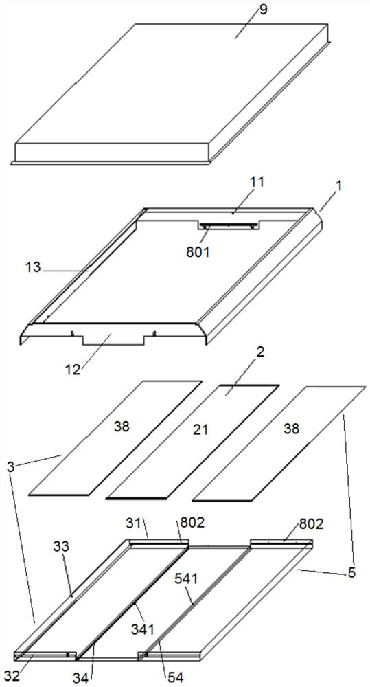
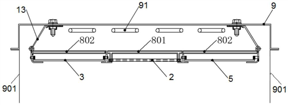
[0059] Such as figure 1 , figure 2 , image 3 , Figure 4 As shown, the elevator ceiling includes a shade frame 1, a central lighting panel assembly 2, and a first side lighting panel assembly 3;

[0060] The shading plate frame 1 is rectangular;

[0061] The first side lighting panel assembly 3 includes a first side support frame;

[0062] A side lighting board 38 is installed and fixed in the first side support frame;

[0063] The upper sides of the front support plate 31 and the rear support plate 32 of the first side support frame are respectively fixed with left and right guide grooves 802;

[0064] The first side support frame is fixedly installed on the right side of the left visor 13 of the visor frame 1, the left part of the front visor 11 and the left part of the rear visor 12;

[0065] A central left support surface 341 bent to the right is formed at the lower end of the right support plate 34 of the first side support frame;

[0066] Such as Figure 5 , ...

Embodiment 2

[0078] Based on the elevator ceiling of Embodiment 1, the front shading plate 11 and / or the rear shading plate 12 of the shading plate frame 1 is provided with a vertical spring limit rod 701 corresponding to the lower part of the vertical groove of the "π"-shaped guide groove 801;

[0079] When the vertical spring limit lever 701 is pressed down, the guide wheel 22 of the central lighting panel assembly 2 is restricted from moving upward along the vertical groove of the "π"-shaped guide groove 801;

[0080] When the vertical spring limiting rod 701 bounces up, the guide wheel 22 of the central lighting panel assembly 2 is allowed to move along the vertical groove of the “π”-shaped guide groove 801 .

[0081] In the elevator ceiling of Embodiment 2, when the central lighting panel assembly 2 needs to be moved up, the vertical spring limit rod 701 pops up, and the central lighting panel assembly 2 is pushed upward to make it follow the vertical direction of the "π"-shaped guide ...

Embodiment 3

[0083] Based on the elevator ceiling of Embodiment 1, such as Figure 12 As shown, the upper sides of the front support plate 31 and the rear support plate 32 of the first side support frame respectively correspond to the right parts of the left and right guide grooves 802, and a transverse spring limit rod 702 is provided;

[0084] When the transverse spring limit lever 702 is pressed down, the guide wheels 22 of the central lighting panel assembly 2 are restricted from moving along the left and right guide grooves 802;

[0085] When the transverse spring limiting rod 702 bounces up, the guide wheel 22 of the central lighting panel assembly 2 is allowed to move along the left and right guide grooves 802 .

[0086] In the elevator ceiling of Embodiment 3, the upper sides of the front support plate 31 and the rear support plate 32 of the first side support frame respectively correspond to the right parts of the left and right guide grooves 802, and a transverse spring limit rod...


PUM


Abstract

The invention discloses an elevator suspended ceiling. A first side lighting plate assembly and a central right supporting surface are mounted on a shading plate frame, and a central lighting plate assembly is arranged on a central left supporting surface and the central right supporting surface of the first side lighting plate assembly. The central lighting plate assembly can slide upwards to a transverse groove of a pi-shaped guide groove along a vertical groove of the pi-shaped guide groove, and then slide leftwards and transversely to left and right guide grooves in the front end and the rear end of the first side lighting plate assembly along the pi-shaped guide groove, so that the central lighting plate assembly is located above the side lighting plate of the first side lighting plate assembly, lighting plate installation, illumination lamp maintenance and daily cleaning can be achieved, the space requirement during emergency rescue can be met, and the overall comfort degree of passengers can be improved through the clean and tidy lift car environment. The invention discloses an elevator car roof.

Description

technical field [0001] The invention relates to an elevator car, in particular to an elevator ceiling and an elevator car roof. Background technique [0002] In the existing car roof structure of the elevator car, the car roof is composed of an upper canopy and a lower suspended ceiling, and the canopy is rigidly connected with the suspended ceiling. When the suspended ceiling is decorated by the lighting board, the lighting fixtures are installed on the sky cover, and the suspended ceiling is composed of surrounding frames and middle moldings supporting the lighting board. When the elevator car space is very narrow, there are many defects in this structure. First, the elevator is a professional equipment, and the installation and disassembly of the lighting panels requires professionals to operate. If there is no fault, professional maintenance personnel will not actively clean the car environment; and due to the limited area of ​​the car, the current installation method o...

Claims


Application Information

Patent Timeline
Patent Type & Authority Applications(China)
IPC IPC(8): B66B11/02
CPCB66B11/0226B66B11/0233
Inventor 万广树吴佳豪姚一
Owner MITSUBISHI ELECTRIC SHANGHAI ELECTRIC ELEVATOR
Why Eureka
Try Eureka