Stretcher type steel spring floating slab track structure

A floating plate and steel spring technology, applied in the directions of track, track laying, track maintenance, etc., can solve the problems of troublesome maintenance, poor practicability, unfavorable damping type vibration isolator maintenance and disassembly and recovery, etc., and is conducive to disassembly, repair and maintenance , Conducive to recycling, and the effect of stable use

Active Publication Date: 2021-08-10
CENT SOUTH UNIV
View PDF6 Cites 0 Cited by
  • Summary
  • Abstract
  • Description
  • Claims
  • Application Information

AI Technical Summary

Problems solved by technology

[0003] At present, when the floating plate is prefabricated, the shell of the damping vibration isolator is usually placed inside the floating plate in advance, and then the damping core and the base are installed. This installation method is not conducive to the maintenance and maintenance of the damping vibration isolator. Disassembly and recycling, when the damping isolator inside a single floating plate is damaged, the entire floating plate needs to be removed, and then the damping isolator needs to be replaced, which is troublesome to maintain; at the same time, it is completely fixed with the floating plate When the damping type vibration isolator of the floating plate vibrates, the damping type vibration isolator is also easy to cause hard damage to the floating plate, resulting in lower overall strength of the floating plate and reducing the service life of the floating plate, which is less practical. Difference

Method used


Image

  • Stretcher type steel spring floating slab track structure
  • Stretcher type steel spring floating slab track structure
  • Stretcher type steel spring floating slab track structure

Examples


Embodiment Construction

[0019] The following will clearly and completely describe the technical solutions in the embodiments of the present invention with reference to the drawings in the embodiments of the present invention.

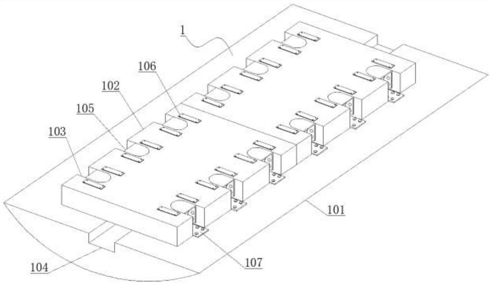
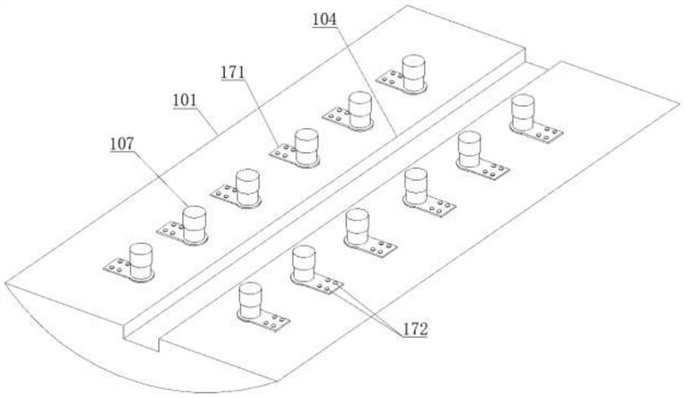
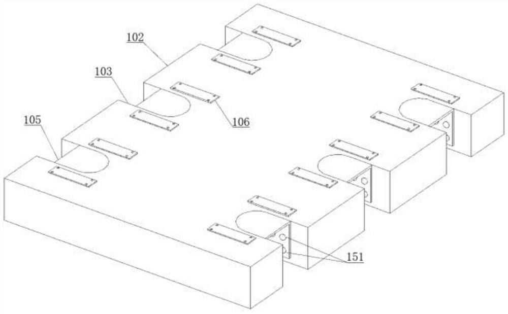
[0020] see Figure 1-Figure 5 , the present invention provides the following technical solutions: a stretcher-type steel spring floating slab track structure, including a track overall structure 1, the track overall structure 1 includes a track support base 101, and the center of the upper surface of the track support base 101 is provided with a base drainage groove 104, and the upper surface of the rail support base 101 is laid with a floating plate 102, and both sides of the floating plate 102 are evenly opened with side-opening installation grooves 103, and the floating plate 102 corresponds to the side-opening installation groove 103 A vibration isolator stretcher 105 is provided at the position, and a floating plate vibration isolator 107 is fixed at the position correspo...


PUM


Abstract

The invention discloses a stretcher type steel spring floating slab track structure. The structure comprises a track overall structure, the track overall structure comprises a track supporting base, a base drainage groove is formed in the center of the upper surface of the track supporting base, a floating slab is laid on the upper surface of the track supporting base, side-opening type mounting grooves are uniformly formed in the two sides of the floating slab, and vibration isolator stretchers are arranged at the positions, corresponding to the side-opening type mounting grooves, of the floating slab. A pre-fixing type vibration isolator mounting mode is canceled, the floating slab with the side-opening type mounting grooves is adopted, the vibration isolator stretchers are fixed in the side-opening type mounting grooves, a vibration isolator is prevented from being directly fixed in the floating slab, and disassembly, overhaul, maintenance and recycling of the vibration isolator are facilitated; and meanwhile, the vibration isolator is not directly attached to and fixed to the floating slab, when the floating slab vibrates, the vibration isolator cannot be directly rubbed and scratched with the vibration isolator, stable use of the floating slab is better facilitated, and practicability is higher.

Description

technical field [0001] The invention belongs to the technical field of railway tracks, and in particular relates to a stretcher type steel spring floating slab track structure. Background technique [0002] The prefabricated floating slab track is to support the ballastless track on the damping vibration isolator (rubber or steel spring) to form a mass-spring system, and the ballastless track is isolated from the inverted arch or other foundation of the tunnel, which greatly weakens the vibration Passing to the foundation, the track is used on the subway and viaduct of the urban track. The common damping type vibration isolator is divided into a shell, a damping core and a base. The damping core is usually a rubber or steel spring. [0003] At present, when the floating plate is prefabricated, the shell of the damping vibration isolator is usually placed inside the floating plate in advance, and then the damping core and the base are installed. This installation method is no...

Claims


Application Information

Patent Timeline
Patent Type & Authority Applications(China)
IPC IPC(8): E01B1/00E01B19/00E01B29/00
CPCE01B1/00E01B1/008E01B19/00E01B29/00
Inventor 黄旭东
Owner CENT SOUTH UNIV
Why Eureka
Try Eureka