Eureka AIR delivers breakthrough ideas for toughest innovation challenges, trusted by R&D personnel around the world.

Optical anti-vibration motor

An optical anti-shake and motor technology, applied in the field of optics, can solve the problems that the driving force and driving stroke of the motor cannot be improved well, the movement stroke is small, and the driving stroke of the motor is affected, so as to avoid impedance, increase the driving force, and improve Effect of Magnetic Density

Active Publication Date: 2021-08-10
北京可利尔福科技有限公司
View PDF12 Cites 1 Cited by
  • Summary
  • Abstract
  • Description
  • Claims
  • Application Information

AI Technical Summary

Problems solved by technology

[0003] However, due to the magnetic attraction force generated between the magnetic piece and the magnet, although the magnetic piece can play the role of magnetic flux, the magnetic attraction force will also affect the driving stroke of the motor
Specifically, when the coil drives the magnet to produce relative motion with the magnet, the magnetic member will generate a magnetic attraction force that resists the drive, resulting in a smaller movement stroke of the optical device when the coil generates the same driving force, so , this setting method still cannot improve the driving force and driving stroke of the motor very well

Method used


Image

  • Optical anti-vibration motor
  • Optical anti-vibration motor
  • Optical anti-vibration motor

Examples


Embodiment Construction

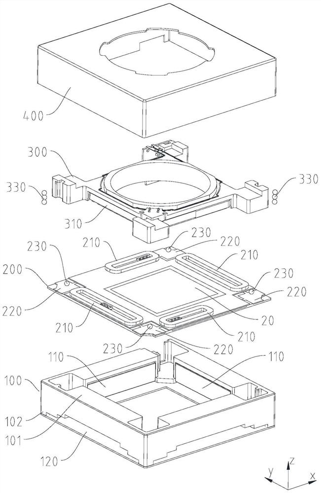
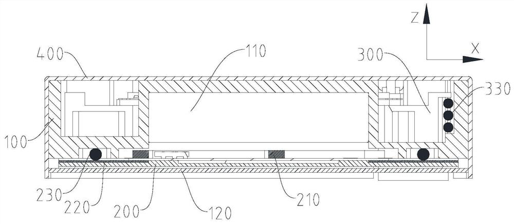
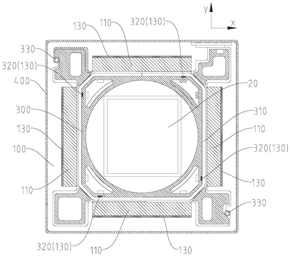
[0059] Specific embodiments of the present disclosure will be described in detail below in conjunction with the accompanying drawings. It should be understood that the specific embodiments described here are only used to illustrate and explain the present disclosure, and are not intended to limit the present disclosure.

[0060] In this disclosure, unless stated otherwise, the orientation words used such as "up, down, left, and right" are defined according to the drawing direction of the drawing, and "inside" and "outside" are for the corresponding parts In terms of its own outline. Terms such as "first", "second" and the like used in the present disclosure are for distinguishing one element from another element, and do not have sequence or importance. In addition, when the following description refers to the drawings, the same reference numerals in different drawings represent the same or similar elements.

[0061] refer to figure 1 and figure 2 , the present disclosure ...


PUM


Abstract

The invention relates to an optical anti-vibration motor, which comprises a first base body, a second base body capable of moving relative to the first base body and a shell covering the peripheries of the first base body and the second base body, wherein a first magnet is installed on the first base body, a first coil is installed at the position, corresponding to the first magnet, of the second base body, the first coil is configured to be capable of generating driving force along an x axis and / or a y axis perpendicular to the x axis so as to make the first base body and the second base body generate relative motion, a first magnetic piece is further installed on the first base body, and is located on the side, opposite to the first magnet, of the first coil, and the relative positions of the first magnet and the first magnetic piece are always relatively fixed, so that the driving force can be increased through the arrangement of the first magnetic piece, the magnetic attraction force between the first magnetic piece and the first magnet does not affect the movement of the second base body, the impedance of the generated magnetic attraction force to the driving force can be avoided, and the motor is ensured to have relatively large driving force and driving stroke.

Description

technical field [0001] The present disclosure relates to the field of optical technology, in particular, to an optical anti-shake motor. Background technique [0002] As users have higher and higher requirements for clear imaging, various functions for improving imaging clarity are introduced into existing camera modules, such as adding optical image stabilization motors or auto-focus motors. Among them, the optical anti-shake motor mostly adopts the method of voice coil control, that is, through the electromagnetic interaction between the coil and the magnet, the displacement of the optical device is controlled in a certain direction to compensate for the shake generated during shooting. In the related art, in order to increase the driving force of the optical image stabilization motor, a magnetic piece is usually installed on the side of the coil facing away from the magnet to concentrate the distribution of the magnetic force lines, thereby improving the driving force of ...

Claims


Application Information

Patent Timeline
Patent Type & Authority Applications(China)
IPC IPC(8): H02K33/12G03B5/00G02B27/64
CPCH02K33/12G03B5/00G02B27/646
Inventor 董怿
Owner 北京可利尔福科技有限公司
Why Eureka
Eureka Blog
Learn More