Current-assisted roll bending forming device and method for ultrathin-wall corrugated plate

An auxiliary roller and corrugated plate technology, which is applied in the field of ultra-thin-wall corrugated plate current-assisted roll forming devices, can solve the problems of aggravating the manufacturing difficulty of ultra-thin-wall corrugated microstructures, poor precision of thin-walled microstructures, limitation of aspect ratio, etc. Important economic and social benefits, the effect of improving plastic deformation performance and improving aspect ratio

Pending Publication Date: 2021-08-13
SUZHOU UNIV
View PDF12 Cites 1 Cited by
  • Summary
  • Abstract
  • Description
  • Claims
  • Application Information

AI Technical Summary

Problems solved by technology

However, in the commonly used roll forming process, the deformation mode of the thin plate is bending and bulging, the roller teeth and the thin plate are mainly in line contact, and the constraints are small, resulting in large bending springback, warpage, etc., and the thin-wall microstructure accuracy is poor. It is difficult to meet the use requirements, and the shape must be corrected by molding, which limits the advantages of thin plate microstructure roll forming. The width ratio is greatly limited; the honeycomb mesh number is high, the microstructure size is less than 1.0mm, and the wall thickness is 30-100μm, which belongs to the category of mesoscopic scale. Fabrication Difficulty of Wall Corrugated Microstructure

Method used


Image

  • Current-assisted roll bending forming device and method for ultrathin-wall corrugated plate
  • Current-assisted roll bending forming device and method for ultrathin-wall corrugated plate
  • Current-assisted roll bending forming device and method for ultrathin-wall corrugated plate

Examples


Embodiment Construction

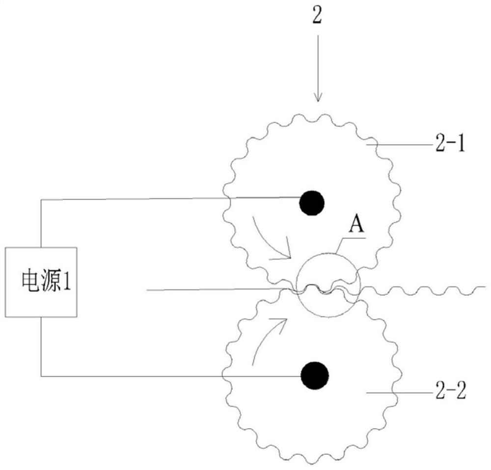
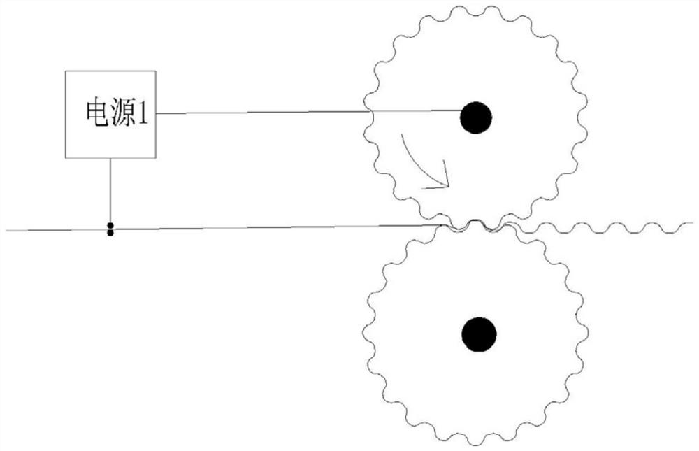
[0039] From figure 1 It can be seen that a current-assisted roll bending device for ultra-thin-walled (thickness 100 μm) corrugated plates (current field-assisted ultra-thin-walled corrugated microstructure roll-forming device) includes:

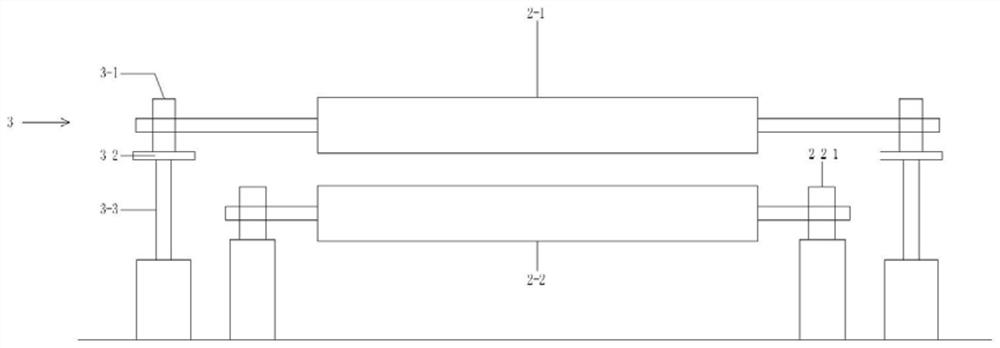
[0040] Power supply 1 (low voltage, high current power supply), microstructure work roll group 2, work roll gap adjustment device 3;

[0041] The microstructure working roll group 2 includes a first roll 2-1 and a second roll 2-2; the surfaces of the first roll 2-1 and the second roll 2-2 are provided with corrugated microstructures; the first roll 2-1, the second roll The vertical distance between the two rolls 2-2 can be adjusted by the working roll gap adjustment device to meet the needs of roll forming;

[0042] The first roller 2-1 is connected with the reducer and the driving motor through a shaft coupling, that is, the first roller 2-1 is driven to rotate by the driving motor; (the second roller 2-2 can be a driven roller, or the sec...


PUM

PropertyMeasurementUnit
thicknessaaaaaaaaaa
widthaaaaaaaaaa
lengthaaaaaaaaaa

Abstract

The invention discloses a current-assisted roll bending forming device and method for an ultrathin-wall corrugated plate, and belongs to the field of roll bending forming machining. The current-assisted roll bending forming device is characterized by comprising a power source and a microstructure working roll set. The microstructure working roller set comprises a first roller and a second roller. Corrugated microstructures are arranged on the surfaces of the first roller and the second roller. One end of the power supply is connected with the first roller and the other end is connected with the second roller. Or one end of the power supply is connected with the first roller and the other end is connected with a thin plate. According to the current-assisted roll bending forming device and method for the ultrathin-wall corrugated plate, the plastic forming limit of the ultra-thin plate is improved, forming springback of an ultra-thin-wall microstructure is restrained, the depth-to-width ratio, the size precision and the like of the corrugated microstructures are improved, and the defects that an existing die forming technology is low in efficiency and small in area, and conventional roll bending forming is small in depth-to-width ratio and large in resilience, and secondary shape correction is needed are overcome.

Description

technical field [0001] The present application relates to the field of roll forming processing, and more specifically relates to a current-assisted roll forming device and method for an ultra-thin-walled corrugated plate. Background technique [0002] The honeycomb structure composed of ultra-thin plate corrugated microstructure has a huge surface area, which is an ideal carrier for catalysts and a key device for automobile exhaust treatment. However, the number of fuel vehicles continues to increase. In 2018, the number of cars in China alone reached 240 million, and the consumption of gasoline reached 140 million tons in 2019. Many regions have successively implemented the "National VI" emission standards, reducing harmful gas emissions. However, environmental problems such as atmospheric pollution, smog and the greenhouse effect are still severe, and there is a long way to go to reduce emissions and carbon emissions. Therefore, facing the "National VII" or even higher ex...

Claims


Application Information

Patent Timeline
Patent Type & Authority Applications(China)
IPC IPC(8): B21D13/04B21D37/16
CPCB21D13/045B21D37/16
Inventor 王春举程利冬马振武贺海东孙立宁
Owner SUZHOU UNIV
Why Eureka
Try Eureka