
Inter-workpiece pin shaft assembling equipment for intelligent manufacturing

A technology for assembling equipment and intelligent manufacturing, applied in the direction of manufacturing tools, hand-held tools, etc., can solve the problems of labor-intensive, low-efficiency, time-consuming, etc., and achieve the effect of avoiding falling and improving accuracy

Pending Publication Date: 2021-08-13
徐相文
View PDF1 Cites 0 Cited by
  • Summary
  • Abstract
  • Description
  • Claims
  • Application Information

AI Technical Summary

Problems solved by technology

[0002] At present, the assembly method of pins between workpieces is mainly manual assembly. This method is a manual repetitive operation. Workers not only need to manually align the pin holes, but also need to push the pins, which consumes people's precious time and a lot of manpower. Reduced work efficiency, so it is necessary to design a pin assembly equipment
[0003] Patent application: CN109014855A, the publication date is 20181218, which discloses a pin shaft assembly device between workpieces for intelligent manufacturing. By fixing the connecting piece on the first fixture and fixing the connecting workpiece on the second fixture, at the same time, the connecting workpiece The pin hole is aligned with the ring signal sensor, the pin hole of the connector is aligned with the signal transmitter, the ring signal sensor transmits the information to the central controller, the central controller controls the motor to stop working, and at the same time controls the inner hydraulic lever to push the pin shaft to the right , the pin shaft is inserted into the connecting workpiece and the pin hole of the connecting piece through the push sleeve groove. The device has a simple structure and is easy to operate, but the intelligent machine will also have deviations, so people need regular maintenance, which consumes manpower.

Method used


Image

  • Inter-workpiece pin shaft assembling equipment for intelligent manufacturing
  • Inter-workpiece pin shaft assembling equipment for intelligent manufacturing
  • Inter-workpiece pin shaft assembling equipment for intelligent manufacturing

Examples


Embodiment 1

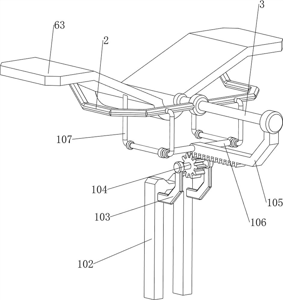
[0071] A kind of pin assembly equipment between workpieces for intelligent manufacturing, such as figure 1 As shown, it includes a bracket 1, a first support frame 2, a push rod 3, a first spring 4, a support mechanism 5 and a feeding mechanism 6, the right part of the support mechanism 5 is provided with a bracket 1, and the bottom right of the feeding mechanism 6 There is a first support frame 2 on the side, and a push rod 3 is slidably arranged on the first support frame 2. A first spring 4 is connected between the push rod 3 and the first support frame 2, and the first spring 4 is wound around the push rod 3. superior.

[0072] When people need to assemble the pin shaft, they can use this kind of smart manufacturing equipment for pin shaft assembly between workpieces. People put the pin hole on the bracket 1, put the pin shaft on the feeding mechanism 6, and then people manually add Move the support mechanism 5 to the right, thereby driving the supporting block 1 and the ...

Embodiment 2

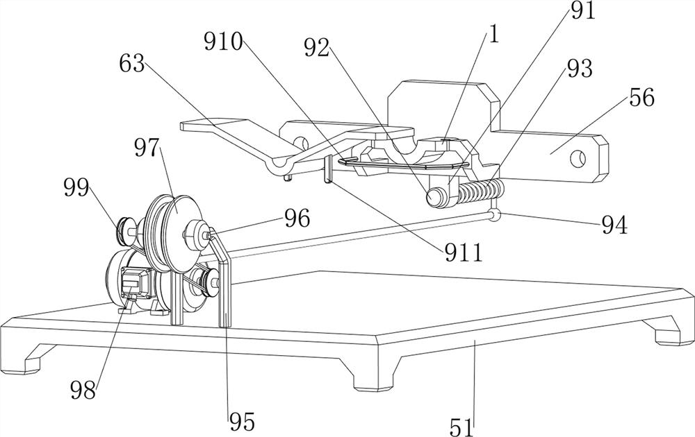
[0074] On the basis of Example 1, such as figure 2 with image 3 As shown, the support mechanism 5 includes a base 51, a second support frame 52, a third support frame 53, a fourth support frame 54, a first slide rail 55, a fifth support frame 56 and a second spring 57. There are four second support frames 52, a third support frame 53 is connected between the two second support frames 52 on the left side, and a fourth support frame 54 is connected between the two second support frames 52 on the right side, The first slide rail 55 is connected to the front and rear sides between the third support frame 53 and the fourth support frame 54, and the fifth support frame 56 is slidingly arranged between the two first slide rails 55, and the fifth support frame 56 is front and rear. A second spring 57 is connected between both sides and the first slide rail 55 on the same side, the second spring 57 is wound on the first slide rail 55 , and the lower right part of the fifth support f...

Embodiment 3

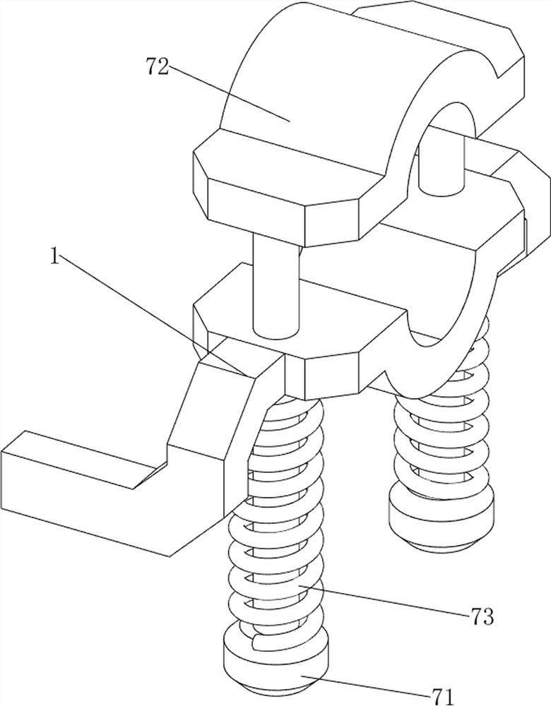
[0079] On the basis of Example 2, such as Figure 4-8 Shown, also include hold-down mechanism 7, hold-down mechanism 7 includes first guide bar 71, pressure block 72 and the 3rd spring 73, all sliding type is provided with first guide bar 71 on the front and rear sides of support block 1, two sides A pressure block 72 is connected between the tops of the first guide rods 71 ​​, a third spring 73 is connected between the two first guide rods 71 ​​and the bracket 1 , and the third spring 73 is wound around the first guide rods 71 ​​.

[0080] After putting the pin hole on the bracket 1, people manually move the first guide rod 71 downward, so that the pressing block 72 moves downward, and the third spring 73 is stretched to achieve the effect of clamping, avoiding the pin shaft Falling in the process of moving to the right improves the accuracy of assembly. When the assembly of the pin shaft is completed, people loosen the first guide rod 71, and the third spring 73 drives the f...


PUM


Abstract

The invention relates to assembling equipment, in particular to inter-workpiece pin shaft assembling equipment for intelligent manufacturing. The inter-workpiece pin shaft assembling equipment for intelligent manufacturing has the advantages of automatic feeding, automatic pressing and automatic assembling. The inter-workpiece pin shaft assembling equipment for intelligent manufacturing comprises a supporting mechanism and a bearing block, a feeding mechanism and a first supporting frame, a push rod and a first spring, wherein the bearing block is arranged on the supporting mechanism; the first supporting frame is arranged on the lower part of the feeding mechanism; the push rod is arranged on the first supporting frame in a sliding manner; and the first spring is connected between the push rod and the first supporting frame, and the first spring is wound on the push rod. According to the inter-workpiece pin shaft assembling equipment, after a pin hole is formed in the bearing block, people move a fifth supporting frame rightwards, so that the bearing block and the pin hole are driven to move rightwards, second springs are compressed, and when the bearing block makes contact with a feeding mechanism component, the feeding effect is achieved.

Description

technical field [0001] The invention relates to an assembly device, in particular to a pin assembly device between workpieces for intelligent manufacturing. Background technique [0002] At present, the assembly method of pins between workpieces is mainly manual assembly. This method is a manual repetitive operation. Workers not only need to manually align the pin holes, but also need to push the pins, which consumes people's precious time and a lot of manpower. Reduced work efficiency, so need to design a kind of pin assembly equipment. [0003] Patent application: CN109014855A, the publication date is 20181218, which discloses a pin shaft assembly device between workpieces for intelligent manufacturing. By fixing the connecting piece on the first fixture and fixing the connecting workpiece on the second fixture, at the same time, the connecting workpiece The pin hole is aligned with the ring signal sensor, the pin hole of the connector is aligned with the signal transmitt...

Claims


Application Information

Patent Timeline
IPC IPC(8): B25B27/02
CPCB25B27/02
Inventor 徐相文
Owner 徐相文
Learn More