
Oil injector

A technology of fuel injectors and actuators, which is applied in the direction of machines/engines, fuel injection devices, engine components, etc., to achieve precise control effects

Active Publication Date: 2021-08-13
SAIC MOTOR
View PDF5 Cites 0 Cited by
  • Summary
  • Abstract
  • Description
  • Claims
  • Application Information

AI Technical Summary

Problems solved by technology

[0003] The purpose of the present invention is to solve the problem that the electronically controlled fuel injector in the prior art can only realize large flow control

Method used


Image

  • Oil injector
  • Oil injector
  • Oil injector

Examples


Embodiment 1

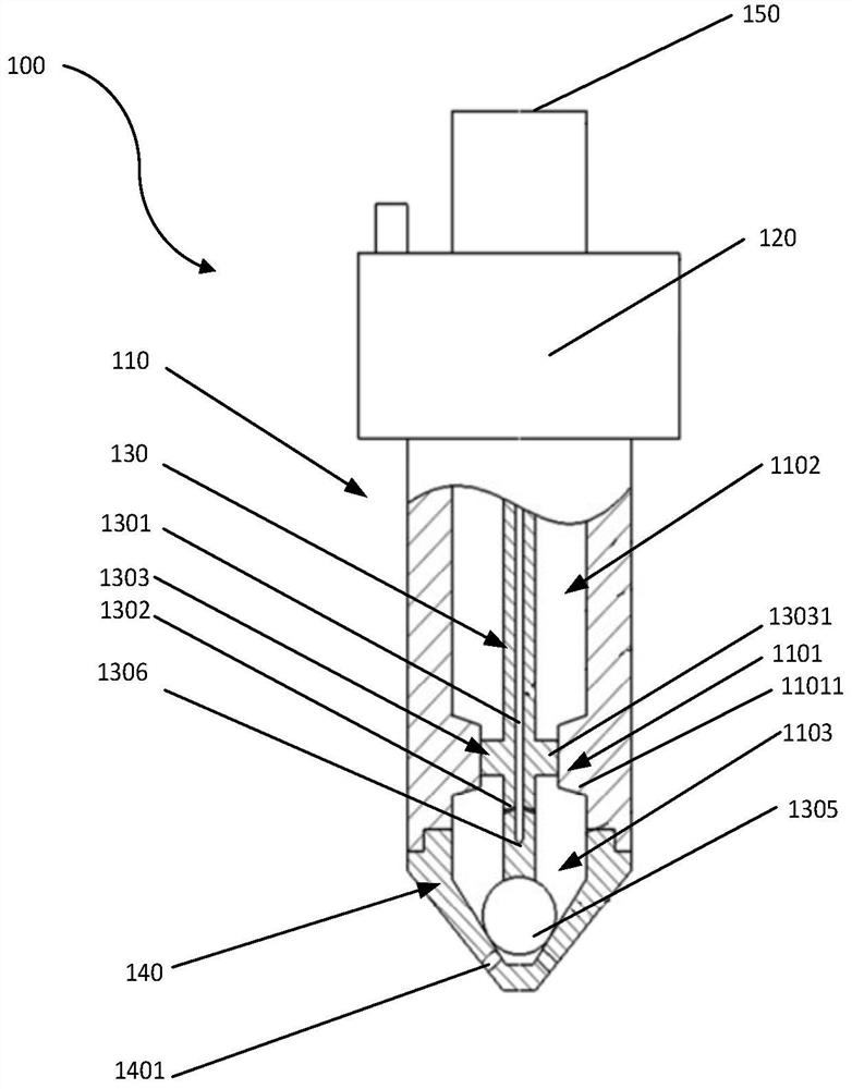
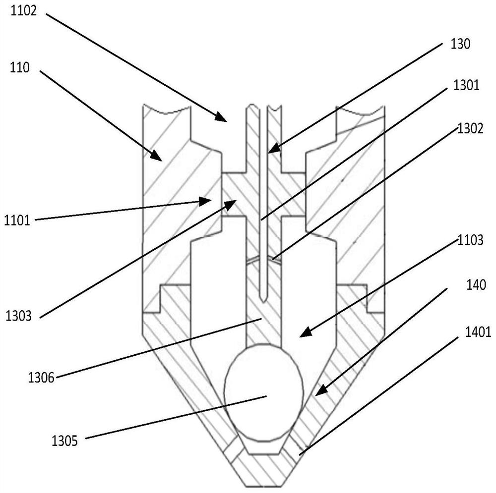
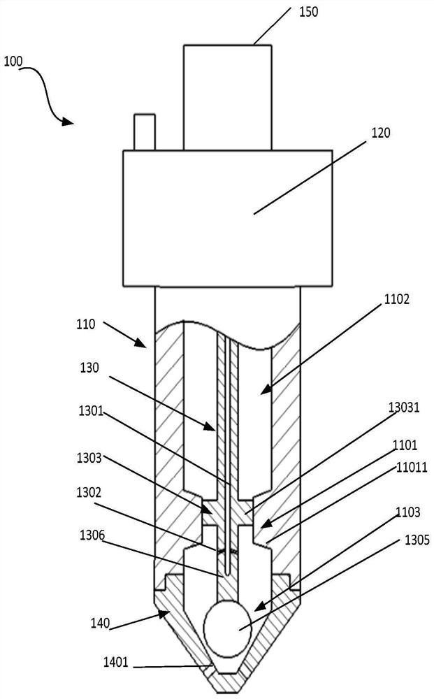
[0062] In order to solve the problem that the electronically controlled fuel injector in the prior art can only realize the flow control in the large flow area, such as Figure 1a-Figure 3 As shown, the embodiment of this embodiment discloses a fuel injector 100, including an actuator 120, a fuel injector body 110, a moving closing body 130, and a valve seat 140; wherein, the fuel injector body 110 has a hollow structure for Accommodates a mobile enclosure 130 . Further, one end of the injector body 110 is connected to one end of the valve seat 140 , the injector body 110 and the inner chamber of the valve seat 140 together form a valve chamber, and the movable closing body 130 can slide in the valve chamber.

[0063] Wherein, the moving closing body 130 includes a valve stem 1306 and a movable restrictor 1303 arranged on the valve stem 1306, and also includes a ball core 1305 arranged on the end face of the valve stem 1306 close to the valve seat 140, and the valve stem 1306 ...


PUM


Abstract

The invention discloses an oil injector. A movable flow limiting part is arranged on the outer circumferential surface of a movable closed body of the oil injector, and a fixed flow limiting part is correspondingly arranged on the inner circumference of an oil injector body. When an actuator controls the movable closed body to move to a first opening position, a first opening communicates with an oil injection outlet flow path, and fuel oil can only flow to a valve seat from a first flow path in the movable closed body through the first opening. When the actuator controls the movable closed body to move to a second opening position, a second opening is formed between the movable flow limiting part and the fixed flow limiting part, and the first opening and the second opening both communicate with the oil injection outlet flow path. Fuel oil can flow to the valve seat from the first flow path in the movable closed body through the first opening and can also directly flow to the valve seat from the second opening. Opening and closing of the second opening are controlled by controlling the position of the movable closed body relative to the valve seat, and therefore two-stage control over large flow and small flow is achieved.

Description

technical field [0001] The invention relates to the technical field of engine fuel injection, in particular to a fuel injector. Background technique [0002] With the rapid development of electronic control technology, electronically controlled fuel injectors are used more and more widely. The widely used electronically controlled fuel injector is to control the opening and closing of the injector needle valve through the electronically controlled actuator, so as to achieve the purpose of controlling the fuel injection flow. The moment when the electronically controlled actuator operates determines the fuel injection phase, and the length of time the actuator is energized determines the size of the fuel injection. Although the widely used electronically controlled fuel injectors respond quickly and control flexibly, compared with mechanical injectors, the control flexibility is improved. The fuel injection pressure, fuel injection phase, and fuel injection volume can be fle...

Claims


Application Information

Patent Timeline
IPC IPC(8): F02M61/10F02M61/18
CPCF02M61/10F02M61/188F02M61/1893F02M61/1873
Inventor 王卓卓
Owner SAIC MOTOR
Features
  • Generate Ideas
  • Intellectual Property
  • Life Sciences
  • Materials
  • Tech Scout
  • Unparalleled Data Quality
  • Higher Quality Content
  • 60% Fewer Hallucinations
Learn More