
A follow-up gravity unloading suspension device

A gravity unloading and suspension device technology, applied in the direction of measuring devices, machine/structural component testing, instruments, etc., can solve the problem of large size range, poor adaptability, inability to simultaneously realize space lens follow-up and complete telescope assembly Splicing tasks and other issues to achieve the effect of good adaptability and high precision of gravity unloading

Active Publication Date: 2022-07-15
BEIJING INSTITUTE OF TECHNOLOGYGY
View PDF8 Cites 0 Cited by
  • Summary
  • Abstract
  • Description
  • Claims
  • Application Information

AI Technical Summary

Problems solved by technology

[0003] However, due to the complex movement of the space mirror assembly on the ground and the large size range, when performing the ground microgravity simulation experiment of the space mirror, the existing space mirror counterweight passive gravity unloading suspension device can usually only move along the A single fixed guide rail moves, and the control of the space lens assembly process is relatively complicated, and the gravity unloading accuracy is not high
In addition, the adaptability of the existing space lens counterweight passive gravity unloading suspension device is not good. It cannot realize the space lens to follow the assembly process and complete the assembly and splicing tasks of the complete telescope at the same time. Many problems have not been well solved. Therefore, there are still higher requirements for the microgravity simulation device in the process of ground simulation assembly and splicing of space lenses

Method used


Image

  • A follow-up gravity unloading suspension device
  • A follow-up gravity unloading suspension device
  • A follow-up gravity unloading suspension device

Examples


Embodiment 1

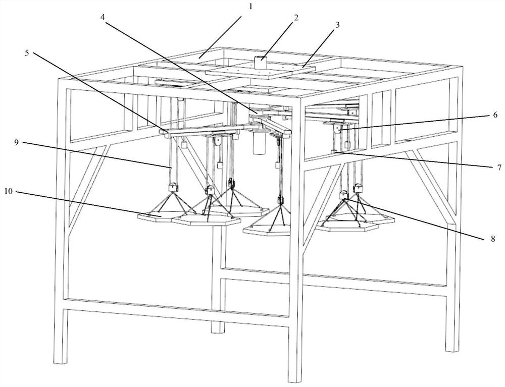
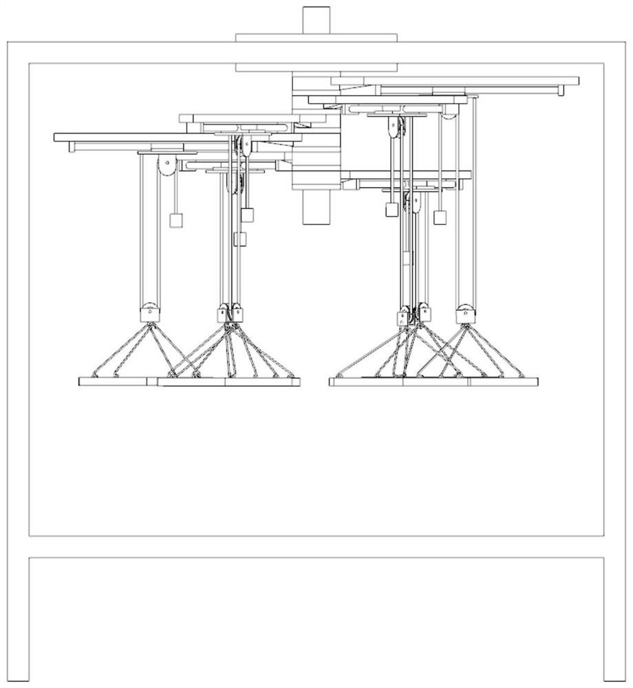
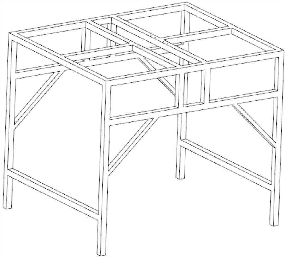
[0036] like figure 1 , figure 2 As shown in the figure, a follow-up gravity unloading suspension device disclosed in this embodiment includes a two-degree-of-freedom suspension bracket and an adjustable suspension device, wherein the two-degree-of-freedom suspension bracket includes a suspension bracket 1 and a vertical column 2 , Pillar fixing part 3, horizontal rotating guide rail 4, horizontal sliding guide rail 5, rolling bearing 2.1; The object of the ground microgravity simulation experiment is the space lens 10 . The counterweight 7 is used to unload the space lens by gravity. The suspension bracket 1 is used to support and protect the entire gravity unloading device. The horizontal rotation guide rail 4 and the horizontal sliding guide rail 5 generate two degrees of freedom in the horizontal direction, and through the rolling bearing 2.1 in the guide rail, the frictionless rotation and sliding of the space lens in the horizontal direction with the assembly process ...


PUM


Abstract

The invention discloses a follow-up gravity unloading suspension device, which belongs to the field of space lens ground microgravity simulation experiments. The present invention includes a two-degree-of-freedom suspension bracket and an adjustable suspension device. The two-degree-of-freedom suspension bracket includes a suspension bracket, a horizontal rotation guide rail and a horizontal sliding guide rail. The adjustable suspension device includes a fixed pulley, a movable pulley, a connecting rope, a counterweight and a space lens. According to the motion process of assembling and splicing simulated on the ground of the space lens, the counterweight unloaded by gravity moves along the horizontal rotating guide rail and the horizontal sliding guide rail to achieve two degrees of freedom movement in the horizontal direction, with a large range of motion, which is suitable for the assembly process, and can be unloaded by gravity. With high precision, the effect of microgravity simulation is closer to the real state of on-orbit assembly of space mirrors. The invention can meet the microgravity simulation requirements of space lenses with different numbers of gravity unloading points and different gravity positions, can adapt to space lenses of different sizes, can follow the assembly and splicing process of space lenses well, and has good adaptability.

Description

technical field [0001] The invention relates to a follow-up gravity unloading suspension device, in particular to a follow-up gravity unloading suspension device used for a space lens ground microgravity simulation experiment, and belongs to the field of space lens ground microgravity simulation experiments. Background technique [0002] As space missions become larger and more complex, satellites tend to carry more and larger payloads, such as advanced large-aperture space telescopes composed of space mirrors, and their functional requirements are becoming more and more stringent. Therefore, the experimental setup required for the simulation of ground microgravity during the simulated assembly process of the space mirror becomes more and more important. At present, the ground microgravity simulation experiments for space lenses are mainly divided into: passive follow-up gravity unloading suspension and active follow-up gravity unloading suspension. Active follow-up gravity...

Claims


Application Information

Patent Timeline
Patent Type & Authority Patents(China)
IPC IPC(8): G01M11/02
CPCG01M11/0207
Inventor 张优藏悦张尧张景瑞安泉王鸿博张祥瑞胡权
Owner BEIJING INSTITUTE OF TECHNOLOGYGY
Learn More