Eureka AIR delivers breakthrough ideas for toughest innovation challenges, trusted by R&D personnel around the world.

Oil-immersed three-phase transformer

A three-phase transformer, oil-immersed technology, applied in the field of transformers, can solve the problems of transformer failure to block fire, increase transformer damage rate, fail to protect transformers, etc., to avoid the spread of fire, reduce gas flow, accelerate The effect of the fire-extinguishing cycle

Inactive Publication Date: 2021-08-13
ZHENJIANG TIANLI TRANSFORMER
View PDF0 Cites 2 Cited by
  • Summary
  • Abstract
  • Description
  • Claims
  • Application Information

AI Technical Summary

Problems solved by technology

[0002] A transformer is a device that uses the principle of electromagnetic induction to change the AC voltage. The most basic form of a transformer includes two sets of coils wound with wires, and they are combined together in an inductive manner. With the rapid development of electric power in our country, A large number of transformers are required for power transmission, but when the existing transformers are in use, it is very easy to catch fire at the wiring of the transformers. At the same time, the traditional transformers do not have the effect of automatic fire extinguishing, and cannot extinguish and alleviate the fire. Increased damage rate of the transformer
[0003] The existing technology has the following disadvantages: when the existing transformer is in use, it is very easy to catch fire at the wiring of the transformer. damage rate, and the traditional transformer cannot block the fire and cannot protect the transformer well, shortening the overall service life of the transformer

Method used


Image

  • Oil-immersed three-phase transformer
  • Oil-immersed three-phase transformer
  • Oil-immersed three-phase transformer

Examples


Embodiment Construction

[0021] The following will clearly and completely describe the technical solutions in the embodiments of the present invention with reference to the drawings in the embodiments of the present invention.

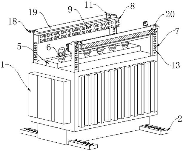
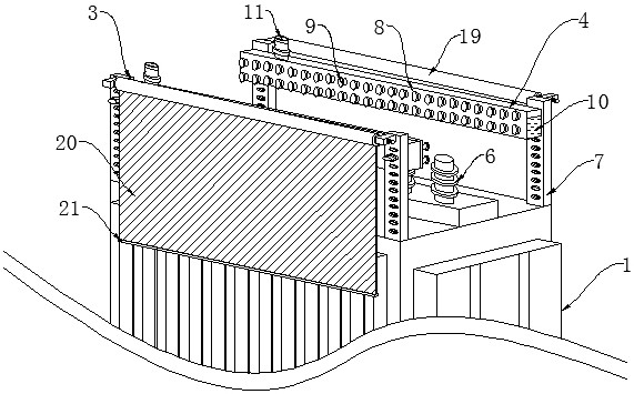
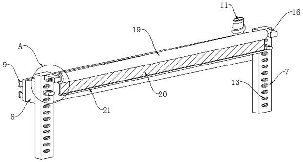
[0022] Such as Figure 1-5 As shown, the present invention provides a technical solution: an oil-immersed three-phase transformer, including a transformer body 1, two sets of extensions 2, two sets of barrier components 3 and two sets of fire extinguishing components 4, the two sets of extensions 2 are installed correspondingly On both sides of the lower surface of the transformer body 1, two sets of fire extinguishing assemblies 4 are installed in parallel on both sides of the upper surface of the transformer body 1, and the output ends of the two sets of fire extinguishing assemblies 4 face the transformer body 1, and the two sets of barrier assemblies 3 Correspondingly installed on one side of the fire extinguishing assembly 4 , and the barrier assembly 3 can be arranged to...


PUM


Abstract

The invention discloses an oil-immersed three-phase transformer which comprises a transformer body, two extending pieces, two blocking assemblies and two fire extinguishing assemblies. The two extending pieces are correspondingly installed on the two sides of the lower surface of the transformer body. The two fire extinguishing assemblies are installed on the two sides of the upper surface of the transformer body in parallel, and the output ends of the two fire extinguishing assemblies face the transformer body. The two blocking assemblies are correspondingly installed on one sides of the fire extinguishing assemblies, and the blocking assemblies can cover the two side walls of the transformer body. The fire extinguishing assemblies are installed on the two sides of the upper surface of the transformer body, the wiring position of the transformer body is fully covered, and the problem that fire is transmitted along wires is avoided. The two side walls of the transformer body are covered with fireproof cloth for fire prevention under the assistance of the blocking assemblies, rapid spreading of fire on the transformer body is avoided, meanwhile, the transformer body can be blocked, gas flowing is reduced, and the fire extinguishing period is shortened.

Description

technical field [0001] The invention relates to the technical field related to transformers, in particular to an oil-immersed three-phase transformer. Background technique [0002] A transformer is a device that uses the principle of electromagnetic induction to change the AC voltage. The most basic form of a transformer includes two sets of coils wound with wires, and they are combined together in an inductive manner. With the rapid development of electric power in our country, A large number of transformers are required for power transmission, but when the existing transformers are in use, it is very easy to catch fire at the wiring of the transformers. At the same time, the traditional transformers do not have the effect of automatic fire extinguishing, and cannot extinguish and alleviate the fire. Increased the damage rate of the transformer. [0003] The existing technology has the following disadvantages: when the existing transformer is in use, it is very easy to cat...

Claims


Application Information

Patent Timeline
Patent Type & Authority Applications(China)
IPC IPC(8): H01F27/40A62C3/16A62C31/02A62C37/36
CPCA62C3/16A62C31/02A62C37/36H01F27/402H01F2027/406
Inventor 李云孙国平金正宁朱巧明王亮
Owner ZHENJIANG TIANLI TRANSFORMER
Why Eureka
Eureka Blog
Learn More